Texacom Veritas walk test

Joined
16 Apr 2026
Messages
4
Reaction score
0
Country
United Kingdom
Hi
Have installed a veritas excel panel with one PIR on zone 1, 1 keypad and 1 bell box.
When carrying out the walk test, the blue light activates on the pir sensor, but is not recognised at the panel .
Similarly , when I set the alarm , it goes through the beeps and then full sets.
When I go into the zone, the pir illuminates blue but does not trigger alarm ?
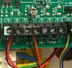
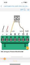
I have wires as red 12v, black 0v, Yellow in A , green in D, with yellow and green connected to zone 1 in the panel. All other zones have tamper links.
Please, what am I doing wrong ??
Thankyou in advance
 
It’s wired wrong …post picture of panel wiring and detector wiring , if you remove one of the wires in zone 1 does it set ?
 
If you are using EOL resistors u need to program this on the panel cant remember which options are required
 
It’s wired wrong …post picture of panel wiring and detector wiring , if you remove one of the wires in zone 1 does it set ?
Hi, thanks for reply . here are photos of the sensor I have , can’t get the pir down but I followed this next diagram. Then the 2 photos inside board, showing the zone 1 connector and the aux.
Many thanks
 

Attachments

  • IMG_3072.png
    IMG_3072.png
    562.4 KB · Views: 6
  • IMG_3073.png
    IMG_3073.png
    342.1 KB · Views: 6
  • IMG_3074.jpeg
    IMG_3074.jpeg
    537.2 KB · Views: 4
  • IMG_3075.jpeg
    IMG_3075.jpeg
    787.9 KB · Views: 6
It’s wired wrong …post picture of panel wiring and detector wiring , if you remove one of the wires in zone 1 does it set ?
Hi, thanks for reply . here are photos of the sensor I have , can’t get the pir down but I followed this next diagram. Then the 2 photos inside board, showing the zone 1 connector and the aux.
 

Attachments

  • IMG_3072.png
    IMG_3072.png
    562.4 KB · Views: 6
  • IMG_3073.png
    IMG_3073.png
    342.1 KB · Views: 6
  • IMG_3074.jpeg
    IMG_3074.jpeg
    537.2 KB · Views: 5
  • IMG_3075.jpeg
    IMG_3075.jpeg
    787.9 KB · Views: 6
Change the slider to zero, wire to a and b that’s inside pir, check it’s unlocked and slide off
 
If you have an r8 plus you can change to use resistors but all devices wired in would need resistors of the same values. Then you can use a to d.
 
Change the slider to zero, wire to a and b that’s inside pir, check it’s unlocked and slide off
Hi, thanks for reply. I’ve now taken pir off, swapped wired to b. When you say slider to zero, do you mean this one ? I have slid it to the top setting looks like 0/C? Is that the one?
 

Attachments

  • IMG_3079.jpeg
    IMG_3079.jpeg
    111.2 KB · Views: 0

If you need to find a tradesperson to get your job done, please try our local search below, or if you are doing it yourself you can find suppliers local to you.

Select the supplier or trade you require, enter your location to begin your search.


Are you a trade or supplier? You can create your listing free at DIYnot Local

 
Back
Top