Texecom PIR problem

Joined
10 May 2019
Messages
4
Reaction score
0
Country
Greece
Hello there, first of all this forum and its threads are very helpful, well done to all contributing!

So, i need your help on setting up a wired PIR for my Texecom Premier Elite 64 wireless.
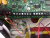
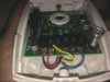
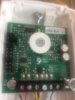
The wireless zones are working perfectly, but a month or so, i am trying to connect a wired PIR in the system but i get the ''Zone 001, Tamper'', i have tried everything but still doesn't work properly.

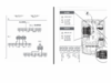
I use EOL wiring,I set the resistor jumpers to 4k2 for alarm and 2k2 for tamper. The zone 001 on keypad is well assigned to the Z-1 on panel, the configuration on keypad is set to EOL/Double Pole wiring.
I even put real resistors in the circuit and changed the cables,changed system config. on wiring but still nothing happens.

Do you have any idea how this could be fixed? Thanks in advance.
 

Attachments

  • rsz_img_0935.jpg
    rsz_img_0935.jpg
    292.1 KB · Views: 551
  • rsz_img_0937.jpg
    rsz_img_0937.jpg
    175.4 KB · Views: 472
Sponsored Links
I think you may have left out a connection at the PIR's terminal block.

Cannot be sure without a circuit diagram of the PIR but I think on the PIR circuit board the alarm switch and it's resistor are connected to W and X and the tamper switch to Y and Z

The Alarm switch and Tamper switch circuits are not connected together on the PCB. This means a link or the 2k2 EOL resistor is necessary between X & Y on the terminal block.

The 2k2 resistor may be on the PCB connected in series with either Y or Z in which case a link is all that is needed

The Alarm and Tamper circuits are separate on the PCB to allow for a 4 wire configuration ( 2 for alarm and 2 for tamper )

I would re-make the connections to get rid of those stray bits of exposed copper and the risk of shorting out the 12 volt supply


0x86.jpg
 
Thanks bernardgreen for your quick reply.
Do you think this diagram helps?
The problem is that on the panel there is only Z1 for alarm (as shown previously) and can't find the seperate tamper circuit
for a 4-wire connections (panel).

As shown on diagram attached,i think my wiring at PIR's end is ok and the jumpers are correctly set.
Yes, and i will tidy up a little bit,thanks.

any further suggestions?
 

Attachments

  • 1.png
    1.png
    197.4 KB · Views: 5,226
Do you think this diagram helps?

It is not the diagram for the PIR. ( diagram has 7 terminals, image of sensor has 6 terminals )

A circuit diagram of the sensor would be more help

kostis3 said:
The problem is that on the panel there is only Z1 for alarm (as shown previously) and can't find the seperate tamper circuit

Z1 is alarm and tamper combined on a single pair of wire. The panel reads the resistance between the blue and yellow wires at the sensor.

If resistance is :-
< 2k2 then fault or cable short = requires repair
2k2 then both switches are closed = no alarm or tamper
6k9 then Alarm switch is open = alarm
> than 6k9 then tamper switch is open = tamper or cable cut
 
Last edited:
Sponsored Links
Wiring looks ok
Photo of pir jumper positions may help ?
Adjust tamper spring on pir and listen for little click sound on pir when you put the lid back on
Tamper could be lid not on correctly?
In engineering mode go to engineer utility press yes scroll down to view zone status press yes
What does it say for zone 001 ?

Secure is all ok
Tamper lid may not be on pir correctly or jumpers not right
 
Thanks once again.
So i believe i am corectly wired into the PCB (2x power + 2x zone - since Z1 is alarm and tamper combined)

Unfortunately can not find any circuit diagram of that PIR
The resistance i get when i did the system diagnostics is that '' Zone 001 Tamper > 65 Κ'' (tamper or cable cut as mentioned)
so again,i re-tried changing cables (they work) and closing tamper switch on pir (+manually) but nothing!

i still miss something!

(i also attach the pic with the jumpers on pir (both on A place...4k7 for alarm, 2k2 for tamper)
 

Attachments

  • IMG_0942.JPG
    IMG_0942.JPG
    219.4 KB · Views: 615
Last edited:
Make sure blue and yellow wires are in zone 1 correctly
The blue and yellow wire need to be on the outer connections of the pir as you have already got
Check the spring on the pir.
If you are in zone status as I have suggested get someone to hold the spring in on the pir while some also looks at keypad to see what is displaying
 
Nope, i was just pressing the spring on the pir, again the same thing.
The blue and yellow wires are well wired on the PCB (as shown on my first post).

the tamper problem still goes on!
 
Did you get a resistor pack with your control panel?
Put a 2.2k resistor in zone 1 on control panel
If tamper fault clears it is a problem with pir jumpers,tamper spring ,fault on cable.
 
4 years later - but I just added a wired PIR to my elite 64 panel using your wiring and jumper settings and it works :)
Thanks so much!
 

DIYnot Local

Staff member

If you need to find a tradesperson to get your job done, please try our local search below, or if you are doing it yourself you can find suppliers local to you.

Select the supplier or trade you require, enter your location to begin your search.


Are you a trade or supplier? You can create your listing free at DIYnot Local

 
Sponsored Links
Back
Top