I would need to check the manual tbh, you can get these online easily enough foc if he hasn't left any.
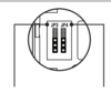
Its something I always forget which jumpers for which values on which detector.
might have to start remembering though as I believe Texecom are going to stop sending out hard copies of manuals and replace it with a Pro app where they can be downloaded.
I have similar app for Risco but the manuals weren't designed for smart phones and can be awkward to use, hopefully Texecom will have pdfs to download and smart phone friendly manuals but that does mean a redesign of the manuals for that purpose.