Using led floodlights on trade stand

Joined
11 Jan 2004
Messages
170
Reaction score
4
Country
United Kingdom
Hello,
I take part at trade shows and want to replace my existing halogen lighting with 50w led floodlights(as image) The lights will be positioned high up behind fascia boards shining down onto the tables set up around the front edge of my stand . Obviously although the lights have a very long life once in a while they will fail and I may need to replace one or two quickly to keep the stand and products well lit.
I am always on a corner and will have two floodlights on each side of the stand shining down and would like the lights in pairs to be connected to one long cable going to the socket(i.e two cable overall going to wall socket.
Firstly can I connect to 50w leds to one cable and secondly is it possible to have each one connected so that it can be quickly "unplugged " and another plugged in to replace it if it fails.Obviously I could just use a very long extension cable with three pin sockets but extensions of this sort are not allowed over 6 feet.
I.e are there male female connectors that are safe and would work in this situation. I hope that all makes sense !
Thanks.
$_10.jpg
 
Sponsored Links
Woodman,
First, as this is for your stand used in exhibitions I would expect that all your wiring has to be installed, tested and approved by an Electrician - rather than you doing the wiring yourself.

With this in mind, I have seen the following used as an inline connector:
https://www.screwfix.com/p/teeplug-ip68-17-5a-plug-socket/38456#product_additional_details_container

Second, there are a lot of dodgy LED lamps like that with no proper earth to case connection and other faults. So again, get good branded version and get them tested and installed by a qualified Electrician.
Here is a nice video showing how bad some are:

Third, LED lights can be very directional (nice round cones of light). Also it is likely that 10W lights will be more reliable than, 25W lights which will be more reliable than 50W lights (the higher wattage LED lights are often over pushed, get hotter and so fail quicker). So you should test first and it MIGHT then be better to get say two 25W lights and space them out.

Fourth, the colour of light these LEDs produce might be different to what you had before, so again you might need to test to make sure it does not effect the look of the items you are showing on your exhibition stand.


SFK
 
Last edited:
Winston,
Yes you are correct, using standard IEC 60309 would be much better.

But I was presuming (and happy to be told if wrong) that he was wanting a 'small/lightweight/discrete' connector actually at each of the LED Lights, so he could quickly remove and replace a light if it fails. I presumed that an IEC 60309 behind the fascia board for each light might be a bit too heavy or cumbersome.

So yes, if he can use IEC 60309, your suggestion would be much better.

SFK
 
Sponsored Links
Thanks for your messages and advice. I would do the wiring and would have them pat tested before the show. As you say they are very tight on this. I actually own a few iec 60309 connectors but to be honest they are pretty big and cumbersome, are they not a bit overkill for two led floodlights that may have joint wattage of not over 100w? The connections would be behind the fascia board but is there not an inline joiner(male and female) that I could use that is much smaller. I would have one half of such a connector permanently connected to the spare light so that I can just swap for the failed one.
I have done a very basic drawing of the sort of thing I mean. As said I want to have both light cables joining into one cable that ends up going to the wall socket ,this saves having loads of cables trailing behind my stand. What would be a good connector for B? For the A connectors would the attached connector be sufficient?
IMG_20170926_0001.jpg

Thanks again for your help.
 

Attachments

  • s-l225.jpg
    s-l225.jpg
    3.3 KB · Views: 190
i have some 2 way iec leads intended to power computers and monitors, in a Y shape
Most LED lights come with 6-12" of cable to which it's easy to add an iec.
otherwise, rewire longer cables. IEC/13A leads are so common, being free with every computer, yet never unwrapped.
people use the old ones.

You are over thinking the failure rate, LED lamps last 100's of hours and aren't delicate.
 
I worked on the shows for a bit, and a reasonably well established exhibition company just used these for their stand wiring.

You have two options, use a distro block and plug two male ends (to fittings) into it and one female (from mains).

The other option is to wire into the female, then out of the female into another female with a short piece of cable and into another female. So you esentially have a Y fitting but if it had been been handwritten lowercase.

The beauty of these is you can use as many leads of xM as you want and plug and play them all to the end with a plug on should you have a different stand. Wire them in white / grey flex though dependant on what shell scheme you generally get

Other much larger companies now have almost an XLR style connector with specially made fuseboards.

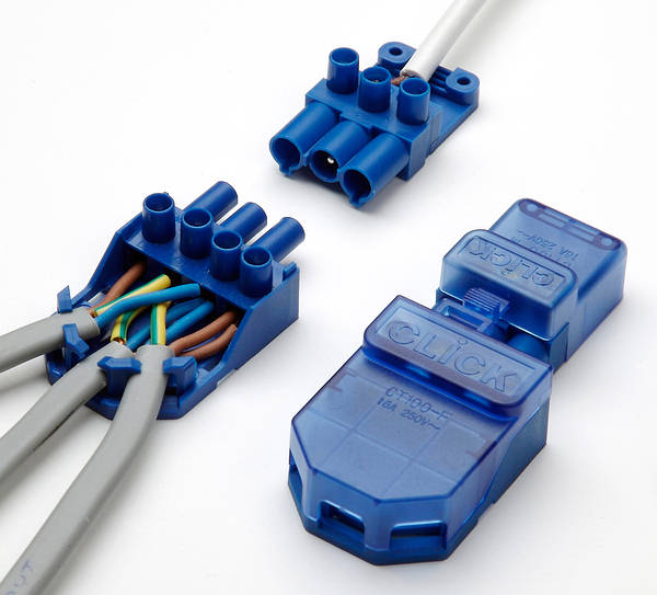
The click flow is rated to 20A so much higher than any standard show circuit.
 
Note that the photo of that connector shows incorrect wiring. The earth should be on central pin and live and neutral on outside pins.
 
Note that the photo of that connector shows incorrect wiring. The earth should be on central pin and live and neutral on outside pins.
The click flow? Thats what the photo shows. It's not wired correctly because one half of the SL+L is in the neutral so if this was connected to a switch, it'd be interesting, but it's not incorrect as your describe
 
Sorry, I meant the image of the
20 Amp Push-in Connector - New Code TLCT101C
That your word 'these' linked to.

Their old image showed the cables randomly pushed in, whereas the 3live wires should go to one pin, the 3 earth wires to the middle and the 3 neutrals to the last pin. For some reason TLC have always shown this image and it has been mentioned a few times on this forum.

But it looks as if they have finally corrected their image - presumably with their new product code. So I stand corrected as I am now wrong.
Sfk
 
Looked at the image again (on my phone) are you sure I am not correct. I am sure the image shows the earth going to the left pin.
But as said, on phone so cannot work out which is the switched live (loop).
Either way, if you use these the earth goes to the center pin.
And should add, I do like these connectors as used the old version several times for down lights - but would be concerned about lack of cable strain relief for this app.
Sfk
TLCT100C.JPG
 
Last edited:
Full-size version

TLCT100C.JPG

The blue on top (which doesn’t even look like it’s terminated) should be sleeved and where the brown from that T+E is, and the brown should be in the far right.

The terminals are, from right to left SL,CPC,N,L. That’s how those cables are lined up (save for the afformentioned mistake)
 
I worked on the shows for a bit, and a reasonably well established exhibition company just used these for their stand wiring.
Seems a bit dodgy.

I doubt they are robust enough for that, one end is not designed to restrain round flex, and ISTR there are no knockouts on the cover - if so then unless there are 3 cables there is access to live parts. And a tool is not needed to gain access to the insides.


Surely IEC 60320 C13/C14s are what's needed?
 

DIYnot Local

Staff member

If you need to find a tradesperson to get your job done, please try our local search below, or if you are doing it yourself you can find suppliers local to you.

Select the supplier or trade you require, enter your location to begin your search.


Are you a trade or supplier? You can create your listing free at DIYnot Local

 
Sponsored Links
Back
Top