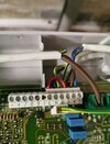
Vaillant ecotec plus 438 no heating or hot water

Sponsored Links
If you have correctly identified the SL as coming from the programmer then, yes, a programmer/wiring fault but the boiler should then just run continuously.

What did you short between and what is "no difference" ?.
No difference = as the boiler nor pump fire up.

I shorted between L and no 3
 

Attachments

  • IMG_20231208_132447.jpg
    IMG_20231208_132447.jpg
    208 KB · Views: 45
That be a progammer issue no? If it's sending voltage when it shouldn't be?

Go read the event chain again posted in this thread.

For systems with wired thermostats:

When needed, Programmes sends a GO signal to the zone in question = 240v ---> Thermostat.
If the thermostat is warm (ie hot enough) the voltage stops there.
If the thermostat is cold, the switch is closed and the 240V continues on to the zone valve actuator.
This energises the actuator which opens the valve fully.
On full open, the valve closes a microswitch connected to a seperate 240V feed. On closing the switch, the 240V is returned to the Boiler SL.
On seeing SL go 240+, the boiler gets the go signal and wakes up.

If you are measuring 240V at the terminal on the boiler marked "SL" and the system components are all marching to that tune, then the boiler should be running.

If you are getting 240V and any one of those links in the chain should be broken (ie you unplugged the programmer, or the thermostat is off) then you have a short circuit somewhere.

Unless the SL is normally 240V+ and detects current changes (odd but whatever) i cant see how you would have SL positive and the boiler sat still.


I am not a plumber/Gas eng. So take this with a pinch of salt.
 
No difference = as the boiler nor pump fire up.

I shorted between L and no 3
Your wiring diagram shows a brown wire, presumably from the programmer? in terminal 3 so shorting between this and the PL (as shown) should start the pump & boiler, presuming you have 230V on the PL??.
But the boiler schematic shows no brown wire in 3 but one in 4 which suggests that this may be the SL?.

1702042251197.png
 
Sponsored Links
Your wiring diagram shows a brown wire, presumably from the programmer? in terminal 3 so shorting between this and the PL (as shown) should start the pump & boiler, presuming you have 230V on the PL??.
But the boiler schematic shows no brown wire in 3 but one in 4 which suggests that this may be the SL?.

View attachment 324356
You have to remove the jumper if using a external control. (IE a 240 signal from a zone valve)

SL then goes to 4.
 
Your wiring diagram shows a brown wire, presumably from the programmer? in terminal 3 so shorting between this and the PL (as shown) should start the pump & boiler, presuming you have 230V on the PL??.
But the boiler schematic shows no brown wire in 3 but one in 4 which suggests that this may be the SL?.

View attachment 324356
The number 4 on mine has been connected to the motorised valve.

Been like this for 15 years and had no problems. Same with all other wiring in wiring centre too.
 
Your wiring diagram shows a brown wire, presumably from the programmer? in terminal 3 so shorting between this and the PL (as shown) should start the pump & boiler, presuming you have 230V on the PL??.
But the boiler schematic shows no brown wire in 3 but one in 4 which suggests that this may be the SL?.

View attachment 324356
Apologies, number 4 was the switched live and voila from L to 4 direct boiler and pump fire up immediately as soon as I turned on mains power
 
The number 4 on mine has been connected to the motorised valve.

Been like this for 15 years and had no problems. Same with all other wiring in wiring centre too.
That is the way it should be
 
That's great, so thats the one to monitor as it comes from the programmer direct or from the 3 port valve orange wire, like below.

1702045156250.png
 
Apologies, number 4 was the switched live and voila from L to 4 direct boiler and pump fire up immediately as soon as I turned on mains power
So go backwards. Go to the switched live from the motorised valve.
It should have permanent live on one side and be switched on the other.
When the valve is open, the switch should close.

Easy to test with a multimeter
 
Thats coming from the 3 port Orange or grey wire.

Yes, the grey wire that comes "directly" from the programmer via the HW cylinderstat is connected in parallel with the orange wire that comes from the 3 port valve when CH only required.

Do the simple test first, with HW only requested and the cylinderstat calling, does the boiler fire up, if so, turn the cylinderstat down, does the boiler then shutdown?
Yes it does fire up and then shuts down when stat is turned down
 
With this amount of testing going on, were it me, I would be making use of something a little more permanent to connect to the SL. Such an item, might be as simple as a small light bulb, a lamphholder, with a bit of flex. Connect the ends of the flex, between SL and N, and it is immediately obvious when there is a call for heat, to the boiler.
 
Very good,
next test, select CH only on, ensure roomstat calling, does the boiler fire up?, if so, turn the roomstat down, does the boiler stop firing?
 

DIYnot Local

Staff member

If you need to find a tradesperson to get your job done, please try our local search below, or if you are doing it yourself you can find suppliers local to you.

Select the supplier or trade you require, enter your location to begin your search.


Are you a trade or supplier? You can create your listing free at DIYnot Local

 
Sponsored Links
Back
Top