Voltage drop at 12V - is there a table?

The arrangement is that at each light there is a transformer. The secondary feeds the lamp. All the primaries are connected in series. The current through them is controlled by the control equipment to alter the brightness.
Yes, I understand that - but,as I've just written to holmslaw, if (as he said) they were '5kv to 12v' transformers, and if the lamps were being supplied with around 12v, one would need a ludicrously high supply voltage for the whole run of transformers. What am I missing?

Kind Regards, John.
 
Sponsored Links
Have a look at the last 15 slides or so in this presentation to see the source equipment
Thanks - that's interesting, but it still doesn't really help me with the voltages. FWIW, the highest voltage mentioned anywhere in that slide set is 2400V - not even enough for the primary of one '5Kv to 12V' transformer, let alone umpteen of them wired in series!

Kind Regards, John.
 
It's ±2400V so 4800V peak to peak.

I expect the transformers are effectively 1:1 current transformers and so will only have a couple of turns on the primary.
 
Sponsored Links
It's ±2400V so 4800V peak to peak. I expect the transformers are effectively 1:1 current transformers and so will only have a couple of turns on the primary.
Quite. The implication of everything I've said is obviously that, whatever else they are, they cannot possibly be "5Kv to 12V" transformers as was suggested. There might be lots of them in series across an approx 5KV supply, hence with fairly modest voltages across each primary - but that doesn't make them "5Kv to 12v transformers"!

Kind Regards, John.
 
Am I the only one bamboozled by the graph on page 7?
How do you get voltage to raise back in time, also to have two levels on the same phase at the same time where it advances after going back??
 
Am I the only one bamboozled by the graph on page 7?
How do you get voltage to raise back in time, also to have two levels on the same phase at the same time where it advances after going back??
No - you're not alone; as drawn, it makes no sense. A sine wave chopped by back-to-back SCRs (or a a triac) looks quite similar to that, except that the upstrokes are more-or-less vertical, not 'backwards sloping' as depicted.

Kind Regards, John.
 
Quite. The implication of everything I've said is obviously that, whatever else they are, they cannot possibly be "5Kv to 12V" transformers as was suggested. There might be lots of them in series across an approx 5KV supply, hence with fairly modest voltages across each primary - but that doesn't make them "5Kv to 12v transformers"!
They are current transformers. So the primary could be up at 5kV whilst the secondary is (presumably) earthed. That's not 5kV over the primary winding of one transformer, the 5kV being what the primary's insulated for.

An open circuit CT can have high voltage over its secondary, but this will be limited by transformer saturation. A saturated transformer will present the primary as a short circuit.
 
They are current transformers. So the primary could be up at 5kV whilst the secondary is (presumably) earthed. That's not 5kV over the primary winding of one transformer, the 5kV being what the primary's insulated for.
No problem with any of that. I guess I'm at risk of being pedantic, but the only reason I brought this up (many posts back) was that they had been described as "5kV to 12V transformers", and there's no way that I would have dreamed of interpretating that as meaning, say, 1:1 current transformer with 5Kv insulation - would you?

Kind Regards, John.
 
I guess I'm at risk of being pedantic, but the only reason I brought this up (many posts back) was that they had been described as "5kV to 12V transformers", and there's no way that I would have dreamed of interpretating that as meaning, say, 1:1 current transformer with 5Kv insulation - would you?
Yes.

The context was of current transformers. Apart from the primary/secondary current ratio and the maximum secondary current, I might want to know the secondary voltage when supplying the rated current and the maximum voltage that the primary is insulated for. Interpreting the 5kV as the voltage over the CT's primary winding is clearly invalid for a CT.

The primary and secondary voltages over CT windings will vary with the current being transformed, so it does not make any sense to refer to primary and secondary voltages.
 
... they had been described as "5kV to 12V transformers", and there's no way that I would have dreamed of interpretating that as meaning, say, 1:1 current transformer with 5Kv insulation - would you?
Yes. The context was of current transformers.
The point is that there was no such context, and that's what confused me. The mention of "5kV to 12V transformers" was in the fifth posting of the 2009 thread referenced above. The OP (ericmark) had expressed surprise about the existence of these transformers, so clearly did not know their function. After two (incorrect) speculations about the possible reason for the transformers (from TTC) and an acknowgement from OP, holmslaw made this first mention of "5kV to 12V transformers". The discussion in the 2009 thread did not once mention 'current transformer', and the first mention of current transformers in this present thread was from you, just two or three posts ago.

In the absence of any contextual pointers to the contrary, I really do think that virtually everyone would make the same assumption that I did in interpreting the meaning of, say, a "230V to 12V transforner", or a "230V to 110V transformer", wouldn't they?

Kind Regards, John.
 
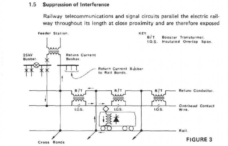
Another use of transformers in current mode is on railway traction supplies to create a return current parallel to the overhead supply cable to reduce the electromagnetic effect from the over head cable.
Interesting. That's clever, although I'm a bit confused as to why the 'cross bonds' between the 'return conductor' and rail do not seriously undermine the good intent of this system.

I am, as you might imagine, well familiar with the concept of current transformers, particularly in the context of instrumentation - but the problem in this thread was that I did not twig (although I suppose I should have done), until Stoday recently pointed it out, that we were taking about current transformers here.

As others have commented, although very clever, this method of powering runway lights seems incredibly complicated (hence costly). Although I assume that all the alternatives were considered, my intuition keeps telling me that 'there must be a simpler way', but I guess there isn't - at least, not with the same features and reliability!

Kind Regards, John
 
Interesting. That's clever, although I'm a bit confused as to why the 'cross bonds' between the 'return conductor' and rail do not seriously undermine the good intent of this system.
The wires at the mid-point of the booster transformers is required to ensure that the current gets sucked up into the return conductor. Without the mid-point connections, the transformer would be open-ended, and no current will flow.

I think I understand what you're saying, but there's a compromise to be had between the cost and losses of booster transformers, and the acceptable amount of current that can go through the rails and not interfere with signalling equipment.

The label 'cross bonds' by the way, is actually indicating the connections to the other tracks on a multi-line railway.
 
Interesting. That's clever, although I'm a bit confused as to why the 'cross bonds' between the 'return conductor' and rail do not seriously undermine the good intent of this system.
The wires at the mid-point of the booster transformers is required to ensure that the current gets sucked up into the return conductor. Without the mid-point connections, the transformer would be open-ended, and no current will flow.
I realise why those connections (which I mistakenly thought were labelled as 'cross bonds') from between the transformers to the rail have to be there - for the reason you give. However, what was confusing me is that (except in the case of the 'last' transformer - i.e. the right-most one in the diagram) there are such connections from both sides of the secondary of each transformer to the rail. To put it one way, all but one of the transformers' secondaries appears to be partially 'shorted out' by the rail.

The label 'cross bonds' by the way, is actually indicating the connections to the other tracks on a multi-line railway.
Thanks for clarifying. I guessed that, but thought that the label was also referring to the connections between transformers to rail.

Kind Regards, John.
 

DIYnot Local

Staff member

If you need to find a tradesperson to get your job done, please try our local search below, or if you are doing it yourself you can find suppliers local to you.

Select the supplier or trade you require, enter your location to begin your search.


Are you a trade or supplier? You can create your listing free at DIYnot Local

 
Sponsored Links
Back
Top