What do you know about this

you could also just use a pen ( plastic ) and push the contactor down... does the same thing with no chance of puting the wires in the wrong place..

I did not want to force the contactor to a position (with a pen) because it might cause damage or dangerous situation. I do what I am sure about and moving the cables is one of them.
 
Any chance we could see a pic of the photocell, ive not seen this sort of setup before and im guessing the contactor is a combined contactor and photocell control unit?? If anyone can elaborate for my own knowledge id be grateful :)

Cheers guys
Dan
 
ERPEC1000.JPG


one of these on a wall somewhere
 
Albert, no offence, but it sounds like you are out of your depth with this.
If you cannot comprehend what is a fairly basic circuit I would leave well alone.
 
fair do's though, a domestic sparky is unlikely to come accross a photocell / contactor arrangement in normal circumstances..
 
fair do's though, a domestic sparky is unlikely to come accross a photocell / contactor arrangement in normal circumstances..

But even someone who supposedly understands electrical circuits in their everyday job must be able to understand such a basic system ?
 
if you've never seen a contactor before, how are you supposed to understand how it works?

same as a three phase motor starter..
or even a star delta starter, motor reversing contactor and so on..

if you don't use them then the first time you see one you have to figure it out..

everyone has to learn sometimes..
 
Coljack & Albert,

If a standard nema socket cell has been used then i cant work out how the contactor side is wired. I have the same arrangement at home switching some garden lighting, and i really think this is all wired wrong. The white T&E is the main in from the mcb, ok so why isn't the black going to the top of the contactor and where does the newer T&E come from, someones been meddling somewhere and it looks like they didn't know what they were doing. Please can you provide a photo of the cell and its connections and the mini cu and its connections.

We should be able to work out the problem then.

All the best
Dan
 
For those who can't understand what is in the picture:

This is a 3 phase contactor. When the coil of the contactor is energised, the top and bottom terminals are connected in pairs - L1/T1, L2/T2, L3/T3, 13/14.
When not energised, none of the terminals are connected to anything else.
In this example, only half of the terminals are needed since this is a single phase setup.

At the top of the enclosure there are 2 cables entering.
The Grey T+E is the supply - brown and blue cores.
The white T+E is the connection to the photocell - switched live and neutral.

At the bottom of the enclosure there are 2 SWA cables.
The red and blue cores connected to the contactor are the live and neutral.
The yellow cores are earth and connected to the separate block along with the sleeved earth wires from the other cables.

When the photocell is on, this energises the coil in the contactor so the incoming supply on the top terminals is connected to the load on the bottom terminals.
 
oh ffs...

the white T+E that has the red and black cores is a switched live and neutral from the photocell... it switches the contactor on...

the black goes to the bottom because it's going to the other side of the coil from the red at the top...

the grey T+E is the live and neutral feed from the CU.. they both go into the top because that's where they should go.. think of the top 3 terminals as the Com of 3 seperate one way switches..

the bottom 3 terminals are the L1's of those same 3 seperate one way switches..

damn beat me to it..
 
Sorry coljack, all i did was ask a question (which is kinda what ppl do on forums), whats your problem :roll:

Anyway now i've looked at the pic with a fresh pair of eyes i can see where i got confused, apologies to anyone offended by my ignorance but i am only human after all. As for what the cause of the problem is my money would be on the photocell.
 
Albert, no offence, but it sounds like you are out of your depth with this.
If you cannot comprehend what is a fairly basic circuit I would leave well alone.

I do not find your remark offending at all but typical... I worked for more than 25 years as a engineer and when I decided to go to college and re-train as an electrician (I was the oldest in the class), I found that most of the class did not ask questions, not because they did understand everything but because it is not cool.

Stupid and e mature attitude, I did not stop asking questions, not always because I did not understand but because I wanted to be sure.

I find that many people carry this "school mentality" all their lives.
ricicle! are you one of them? I hop not.

I don't see any problem in admitting that I you do not know or sure about something, I guest what it was, the internet did not provide the data I looked for and so I looked for information somewhere else (this forum).

From the point of making sure about something to being ignorant and incompetent in understanding electrical circuit is a bit over the top and completely out of order.

I always do my homework before doing a job and it does not matter how many times I have done it before. I do a job ones, never had to go back for correction.

ricicle, you have the right to think what you want to think, just consider that you might be completely wrong!!!

I was very happy that I brought up this issue because it just proved my point, some one else learned or reminded some new or that was forgotten.
 
Sorry coljack, all i did was ask a question (which is kinda what ppl do on forums), whats your problem :roll:

Anyway now i've looked at the pic with a fresh pair of eyes i can see where i got confused, apologies to anyone offended by my ignorance but i am only human after all. As for what the cause of the problem is my money would be on the photocell.

Please read my reply, and continue to ask questions!!!
 
Sorry, I was having a bad day, having gotten a letter asking me to attend a meeting to finalise my redundancy...

I was a little miffed that, after answering the questions you just asked, in the first reply to this post that I had to re-itterate...

I'd already said that the red and black wires from the white cable were the controlls...
 
dannyboi2003";p="1151052 said:
Coljack & Albert,

If a standard nema socket cell has been used then i cant work out how the contactor side is wired.
I have the same arrangement at home switching some garden lighting, and i really think this is all wired wrong. The white T&E is the main in from the mcb, ok so why isn't the black going to the top of the contactor and where does the newer T&E come from, someones been meddling somewhere and it looks like they didn't know what they were doing. Please can you provide a photo of the cell and its connections and the mini cu and its connections.

We should be able to work out the problem then.

All the best
Dan

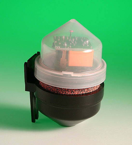
The existing configuration is as follows:
White t&e red coming from the sensor and connected to the control of the contactor (top left), the black (neutral) is in the bottom right (behind no 14).
The supply to the sensor is from the 6A MCB, the red is from the MCB (white t&e)and it is really the L/S from the sensor (makes sense).
The Grey t&e is the supply to the light circuits, this is the in power. Brown in no L1 (could be any of the Ls) and blue in L3 (could be any of the Ls)
The 2 reds on the bottom (T1) are the Live for the circuits, and the blue of course are the neutrals.
When the sensor is activated the contactor makes the contact between L1 to T1 and L3 to T3. Light circuits are energized and if no problems, lights will come on.
But the contactor trips, this is because when day light and the power was turned on it will work for a short while and than go off until it becomes dark enough.
I bypassed the sensor and the MCB tripped, I think that this is the result of the snow and a lot of rain. one or more of the connections inside the light polls has a connection problem.

I left the site and did not continue with the job, as I realized that few months ago an intervention took place by an electrician who supposed to re-do all and make it safe. The customer told me that, and said that if I do not mind he will try to contact the previous electrician, the electrician was paid a lot of money and this work is not up to the standard, and he wants him to correct it. I said that this is ok and although I understand perfectly well the configuration and could easily continue I thought that the customer should not pay again for this job. Although he offered me I did not charge him for the time I spent on site .
 

If you need to find a tradesperson to get your job done, please try our local search below, or if you are doing it yourself you can find suppliers local to you.

Select the supplier or trade you require, enter your location to begin your search.


Are you a trade or supplier? You can create your listing free at DIYnot Local

 
Back
Top