What to ask sparky?

Joined
19 Jun 2009
Messages
274
Reaction score
7
Country
United Kingdom
I plan to have a go at some electrics in a flat I am re-organising.

Essentially, I will be removing a bathroom and relocating it to a part of a an existing kitchen area, and the bathroom will become a separate habitable room.

I have to notify Building Control as I will be doing some electrics, moving a water tank into the attic, and making a loft larger.

The electrics I am planning to do is to add some sockets to a ring, and the light stuff for the bathroom and kitchen. I am fairly conversant with the regs in terms of ring main and lighting.

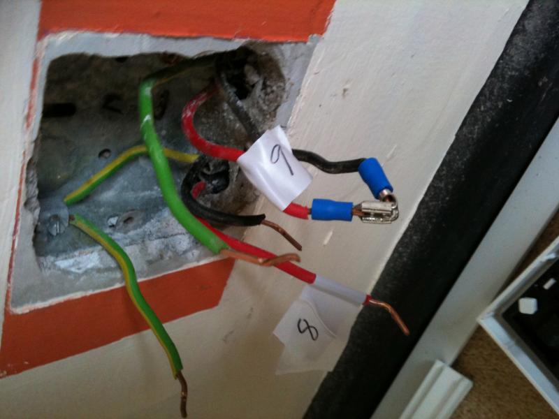
I was thinking of putting in a new ring, but looking at the flat, much of the wiring goes under a concrete floor. I think it better to simply adapt the current ring for my purposes. One issue is the socket in the kitchen, which will now become the bathroom. I aim to eliminate this socket, by disconnecting both feeds into the socket (which will remain live), and then systematically disconnecting, one at a time, each likely feed from other sockets. When the original disconnected feed goes dead, it implies it must be fed by the recently disconnected feed from the other socket. I will do this for both feeds into the original socket. That will enable me to identify what two other sockets feed this one, and I can use that info to feed a new socket somewhere else.

1. Does that sound a sensible course of action?
2. Is there anything wrong with that?
3. I intend to leave the existing (dead) feeds buried in the ground.

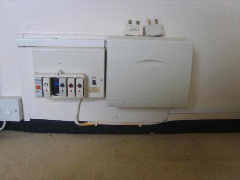
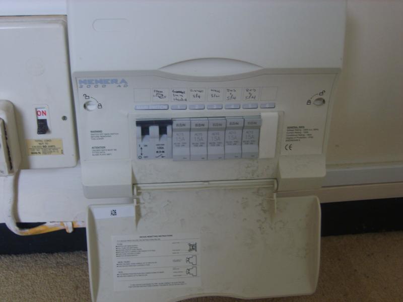
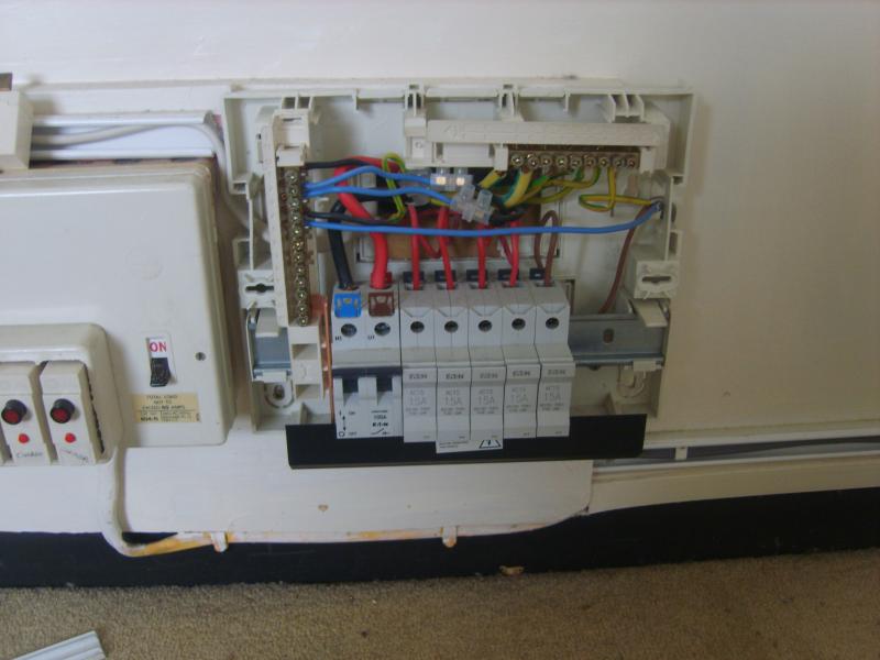
I also have a consumer unit that needs replacing and could do with some advice - I don't intend to tackle this myself, as it is beyond my scope.

Here are some pics :


The unit on the left feeds the sockets, lights and electric shower, and the one on the right feeds each individual electric heater in neach of the rooms.

4. Do I ask spark to replace the whole lot with one unit, or just the one on the left, and leave the one on the right?

5. Finally, when I do my lights for the bathroom, is it still OK to have a standard switch on the outside of the room for the light and the fan (I don't like pull cord switches)

Thanks for your help.
 
Sponsored Links
Do not disconnect cables while they are live !!!

You need to ensure continuity of the ring after you have finished. How will you go about this ?

Are the electric heaters on an off peak supply - if so it will usually remain as a seperate board.

Nothing wrong with a switch on the outside of bathroom.

Don't forget the notification !!
 
< Do not disconnect cables while they are live !!! >

Yes, I meant I would disconnect them (when they are dead) and then make them live to test them - if they remain dead, then I have found the feed.

< You need to ensure continuity of the ring after you have finished. How will you go about this ? >

I would inform Building Control of the work I intend doing, I would then do the work, and then get a spark to do the consumer unit and do the test to comply - I assume that I can do Bathroom and Kitchen work if I notify Building Control, but would need someone to do the other stuff and test it before BC sign off?

< Are the electric heaters on an off peak supply - if so it will usually remain as a seperate board. >

OK - I think the immersion heater is on OFF Peak - not sure about the heaters.

< Nothing wrong with a switch on the outside of bathroom. >

Thank You.

< Don't forget the notification !! >

I won't forget! - looking at the local council's website, it will cost me about £200 for a Building Notice. If and when I sell it, I will need to show proof of work. The landlord has already agreed to the work and as the rooms are changing, it won't match the lease plans. If I sell, and during any conveyancing only a fool would not notice the work done!

_________________

Another question - if I can trouble anyone further - I plan to relocate the water tank to the loft space. Am, I right in thinking I can do this myself along with the other stuff provided I notify BC?
 
Yes, I meant I would disconnect them (when they are dead) and then make them live to test them - if they remain dead, then I have found the feed.
Noooooooo.....

Use a continuity tester to identify lengths of cable.


I would inform Building Control of the work I intend doing, I would then do the work, and then get a spark to do the consumer unit and do the test to comply
1) You need to ensure that your LABC is happy with that
2) Much more significantly you need to ensure that your electrician is happy with that. You need to involve him right from the start, and clear everything with him before you do it. Basically if you think you can just do a load of work and then get an electrician to produce a certificate for it which will satisfy the council then you're probably going to crash and burn.


I assume that I can do Bathroom and Kitchen work if I notify Building Control, but would need someone to do the other stuff and test it before BC sign off?
If you notify you can do the lot, depending on what your council require in the way of certification and how competent they judge you to be.

But you'll be paying £200 to the council, then paying an electrician to check your work (which in reality will mean also paying him to advise you first) and then paying the electrician to do various other work.

Are you sure it wouldn't be cheaper to have a registered electrician do the lot?


Another question - if I can trouble anyone further - I plan to relocate the water tank to the loft space. Am, I right in thinking I can do this myself along with the other stuff provided I notify BC?
I don't think that moving water tanks is notifiable, but you can check here.
 
Sponsored Links
Thanks.

< Use a continuity tester to identify lengths of cable. >

I think I see - keep all circuits dead, disconnect the cables, connect live to neutral? (when dead), and test for resistance on another pair of live and neutral wires? The one that has little resistance is the cable concerned. If this is right, that seems nice ...

< But you'll be paying £200 to the council, then paying an electrician to check your work (which in reality will mean also paying him to advise you first) and then paying the electrician to do various other work. >

Yes, but I will be doing building work as well - as so will still need to involve Building Control, and the BC costs can be lumped together.

Your other points are noted - thanks.
 
Get on the phone, find a sparky willing to work with you, and to supervise what you are doing, if they are a member of the competent persons scheme they can notify their own work, or may be willing to notify things you do if they get to inspect them and you do as they ask. This will save you the LABC fee and also you get your work checked for compliance as you go.
 
Thanks John.

Thanks BAS for pointing me to a continuity test on the wires, and I thought I'd just update fully what you meant, as this was very useful for me to identify everything that is happening on the ring main.

Anyone who wants to know how their sockets feed one another might wish to know this also.

ALL POWER POWER OFF

Essentially I disconnected and exposed all the wires from every socket.

1. I started on one of the sockets, and chose one of the cables. I connected the live and neutral of this cable together (using an e.g. crocodile clip) and mark this cable with the number "1" (indicating the first cable), leaving the other live/ neutral feed alone.

2. I then get my multimeter, and set it to resisitance mode (ohms), and go to another socket. Assuming no spurs, there will be two cables feeding each of the sockets. I check each pair in turn, by connecting the multimeter to the live and neutral of that cable. If there is high resistance it means that that cable is not being fed from the socket where I connected the live and neutral together, and so I move on to the next socket. Once I find a live/neutral with zero resistance, I know that cable is being fed from the socket where I connected the live/neutral together. So I also mark this cable with the number "1". I stay at that socket, and move on to the other cable feeding the socket. I mark this cable with the number "2" and connect its live/neutral together (having disconnected the crocodile clip from live/neutral from cable numbered "1").

3. I then move on to another socket to find which cable shows zero resistance. Once I find that cable, I number it "2", stay at that socket and label the other cable "3", and continue.

I have almost identified my whole ring main, which will help me identify what I need to do to progress the project with BC.

This is an image from a socket where I have already identified cable "8", I have just labelled cable "9", connected its live/neutral together, in order to move to another socket to find the cable that has zero resistance on the multimeter.

Multimeter shows zero resistance once you have found the cable which feeds that socket.

... or high resistance if you have not closed the circuit.

Spurs aren't a problem, because while there are three cable, one of them will feed a socket with only one cable, and you can identify this in the same manner.

... CARE
Make sure you have disconnected all of the cables to all of the sockets, otherwise you will have more than one socket which looks like it feeds the socket you are interested in. You may also have shaving sockets etc to think about ...
 
Now all you have to do is learn how to do the figure of 8, Ring Final Continuity testing - for when you connect all those sockets back on and want to confirm continuity and polarity :LOL:
 
< Now all you have to do is learn how to do the figure of 8, Ring Final Continuity testing - for when you connect all those sockets back on and want to confirm continuity and polarity >

Ah ha - nice one!

http://www.tlc-direct.co.uk/Book/8.4.2.htm

That is amazing, and so obvious when you see it ...

Thanks.

I have just ordered Whitfield's 17th Edition.

Pretty informative, although we don't normally do Test 1 in that manner, it will still confirm continuity of the conductors. :)

The only info I will add to that is that, during Test2, as long as you get a reading during both parts of the test (at every socket outlet), you will also have confirmed polarity as well.

To give you an idea of what I mean:

If during the line and neutral cross-connection, you don't get a reading at a particular socket, yet you get a reading at the same socket during line & CPC test, then you have the line conductor and CPC in the wrong terminals at that socket.

If during the line and CPC cross-connection, you don't get a reading at a particular socket, yet you get a reading at the same socket during line & neutral test, then you have the line conductor and neutral conductor in the wrong terminals at that socket.

If you don't get a reading for either at a socket, then you have the neutral conductor and CPC in the wrong terminals.

Hope that makes sense. :)
 
Thanks.

Been thinking about this a bit more.

Firstly, in Test 1, the resistance should agree with the table.

Can I still stay with test 1 for a minute, and test the sockets (although it doesn't say so in the link)

So staying with Test 1 (and leaving one Live and one Neutral disconnected at the CU), and moving the ohmeter to each socket to test the L/N, I should see (even with Test 1), that the resistance should be similar for each socket (since, by moving to the next socket, I make the distance of the Live wire in the completed circuit shorter/longer by X metres, but also correspondingly make the distance of the Neutral wire longer/shorter by the same amount (X metres). => same amount of copper in circuit => same amount of resistance for each socket. If I get to a socket that has high resistance, then the Live/Neutral must be swapped because the circuit is not complete.

Is it right that in test 2, if there is a bridge, then a set of sockets would show roughly the same reading and another set of sockets would show roughly another reading. Those sockets "within the bridge" showing a lower resistance (less copper in circuit) and those outside the bridge showing a higher resistance (more copper in circuit).

I'll bear your comments in mind if my readings look odd ... which I will only find out in a few weeks once I have finished my planning and start the work.

Thanks so much - I am trying to learn all the time.
 
Thanks.

Been thinking about this a bit more.

Firstly, in Test 1, the resistance should agree with the table.

Can I still stay with test 1 for a minute, and test the sockets (although it doesn't say so in the link)

So staying with Test 1 (and leaving one Live and one Neutral disconnected at the CU), and moving the ohmeter to each socket to test the L/N, I should see (even with Test 1), that the resistance should be similar for each socket (since, by moving to the next socket, I make the distance of the Live wire in the completed circuit shorter/longer by X metres, but also correspondingly make the distance of the Neutral wire longer/shorter by the same amount (X metres). => same amount of copper in circuit => same amount of resistance for each socket. If I get to a socket that has high resistance, then the Live/Neutral must be swapped because the circuit is not complete.

This would only be true with the Line and Neutral test, as the CPC is a different cross sectional area, so less copper = more resistance :)

To be honest, you're best forgetting Test 1 in your link and doing this:

Disconnect the 2 x line conductors, 2 x neutral conductors and the 2 x CPCs at the CU.

Take a continuity reading between one end of the Line conductor and the other end of the Line conductor.
This is called the 'end to end' test and will confirm the continuity of the conductor.
Repeat this for the other two conductors.
The Line and Neutral conductor readings should be roughly the same, the CPC reading will be higher.

If you don't get a reading, you have a break in that conductor somewhere around the ring :)

Now you can proceed with Test 2 from your link.

.

Is it right that in test 2, if there is a bridge, then a set of sockets would show roughly the same reading and another set of sockets would show roughly another reading. Those sockets "within the bridge" showing a lower resistance (less copper in circuit) and those outside the bridge showing a higher resistance (more copper in circuit).

This is roughly correct, and a socket on a spur should give a higher reading.

A little tip: When you have completed the cross-connections for the tests in Test2, (say using two single connector blocks), if you take a reading between the two connector blocks (at the CU), this reading will be roughly what you should expect to get at each socket.

Then, if you get a significantly lower reading than this at a socket, that socket could be on an interconnection.
If you get a significantly higher reading than this at a socket, chances are the socket is a spur.

I feel like I'm betraying the 'magic circle' here. ;)
 
<A little tip: When you have completed the cross-connections for the tests in Test2, (say using two single connector blocks), if you take a reading between the two connector blocks (at the CU), this reading will be roughly what you should expect to get at each socket.>

Ok - that makes sense to me

<Then, if you get a significantly lower reading than this at a socket, that socket could be on an interconnection.>

When you say interconnection, do you mean bridge (as Whitfied's drawing)? If so, your statement is testing me a bit (I usually get confused!) ... when I draw it out, it seems that if there is a bridge, and with both connector blocks cross-connected L/N at the CU, I thought I'd see a resistance equal to the resistance of the sockets that lie within (and before) the bridge, because the length of circuit is the same. Those sockets outside the bridge would be of a higher resistance? Perhaps I don't exactly know what interconnection means or probably am drawing it wrong?

<If you get a significantly higher reading than this at a socket, chances are the socket is a spur.>

Yes, understand that.

<I feel like I'm betraying the 'magic circle' here.>

Don't worry - ever see "Pay it Forward" - you are making the world a better place!

P.S. Before I started thinking about this project, I never thought I'd want to tackle a CU, but this has whet my appetite, and if the Whitfield book makes sense when I get it, I might give it a go and lump it in with the other stuff when I put my plans to BC.

Thanks again.
 

DIYnot Local

Staff member

If you need to find a tradesperson to get your job done, please try our local search below, or if you are doing it yourself you can find suppliers local to you.

Select the supplier or trade you require, enter your location to begin your search.


Are you a trade or supplier? You can create your listing free at DIYnot Local

 
Sponsored Links
Back
Top