- Joined
- 8 Oct 2020
- Messages
- 47
- Reaction score
- 0
- Country

Paid an architect a substantial amount of money to do the designs for two large extensions on my house. They're both two-storey extensions and there are multiple posts and UBs and UCs of a wide range of sizes and lengths, all connected together that form the basis of the extensions. It will be a wooden panel with cladding build rather than traditional brick/block.
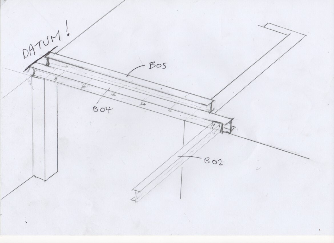
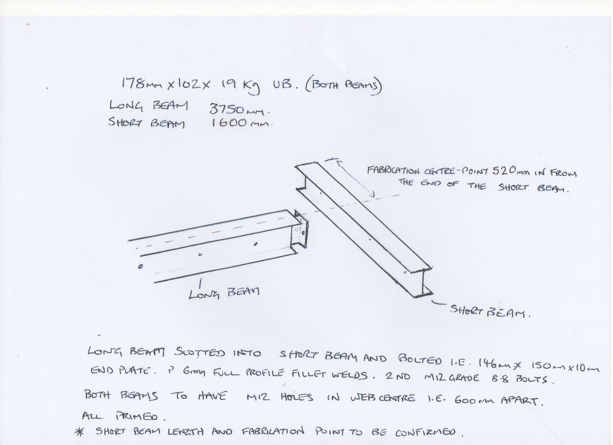
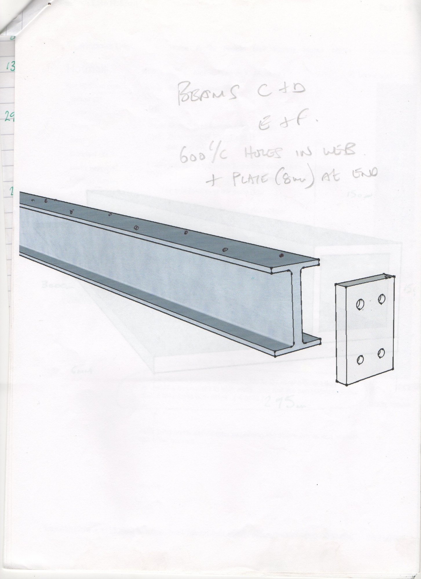
His drgs make reference to the steels needed and there is the usual (in my experience) scruffy hand written in 9B pencil, scanned, photocopied and issued (no checks or approvals signed) bunch of steel calcs and a few hand-drawn scratch/detail drgs showing a couple of the specific connections between members from the Engineer (that the architect commissioned, so a subby to him) and some crude and basic arrangement plan views within their pack to.
It's taken me a few hours to piece the steel calcs/drgs and the architect's drgs together to determine how it all goes together, although I'm still a bit unsure in some areas and I'm not convinced it all works yet.
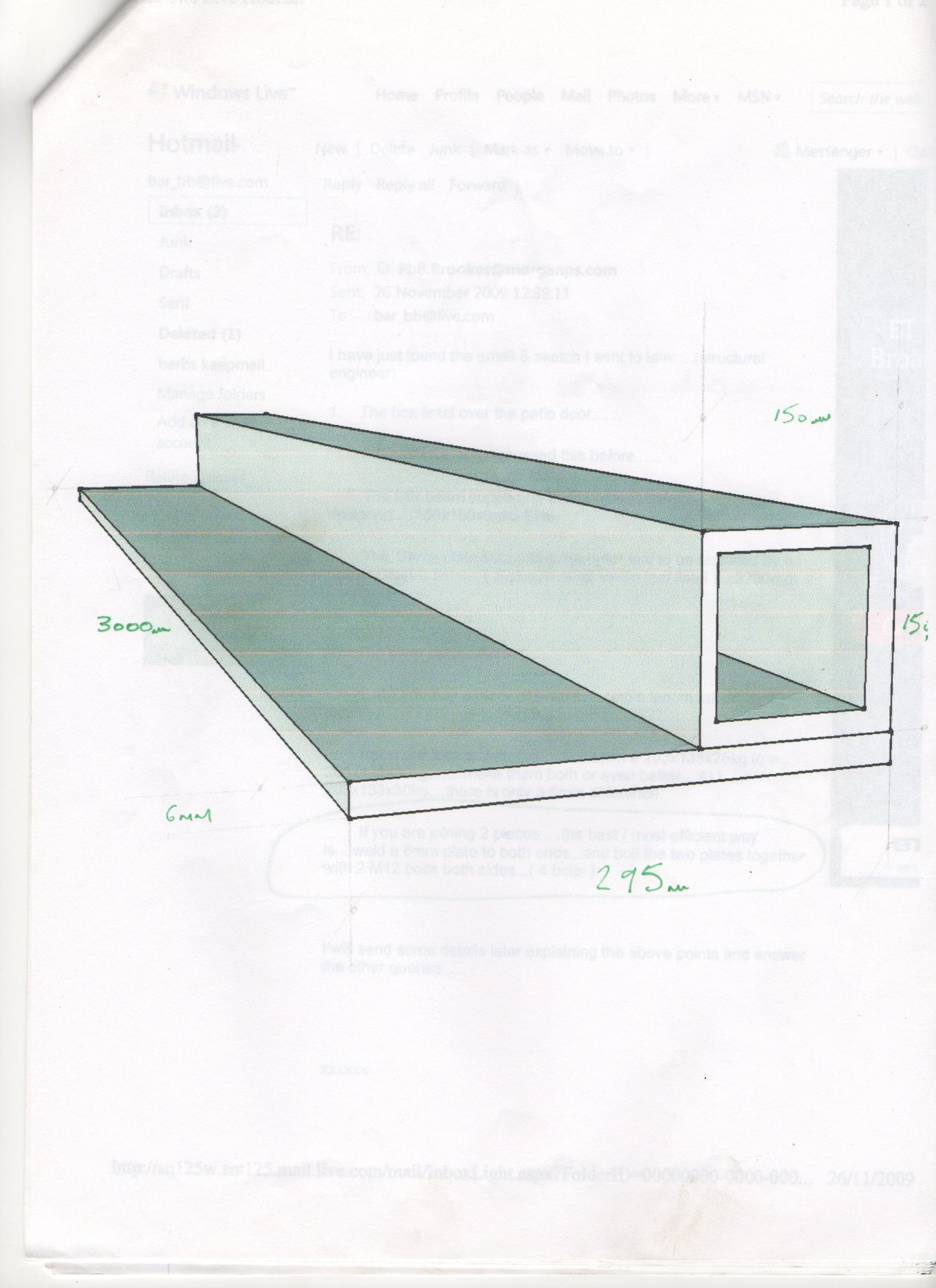
Nowhere, between the two packs of info, are there drgs that would enable a steel fabricator to know what to fabricate, I'm talking dimensioned drgs for each piece of steel and the various posts, with each of the connections and tabs and holes and foot plates etc detailed on it and some sort of indication how each piece connects to another.
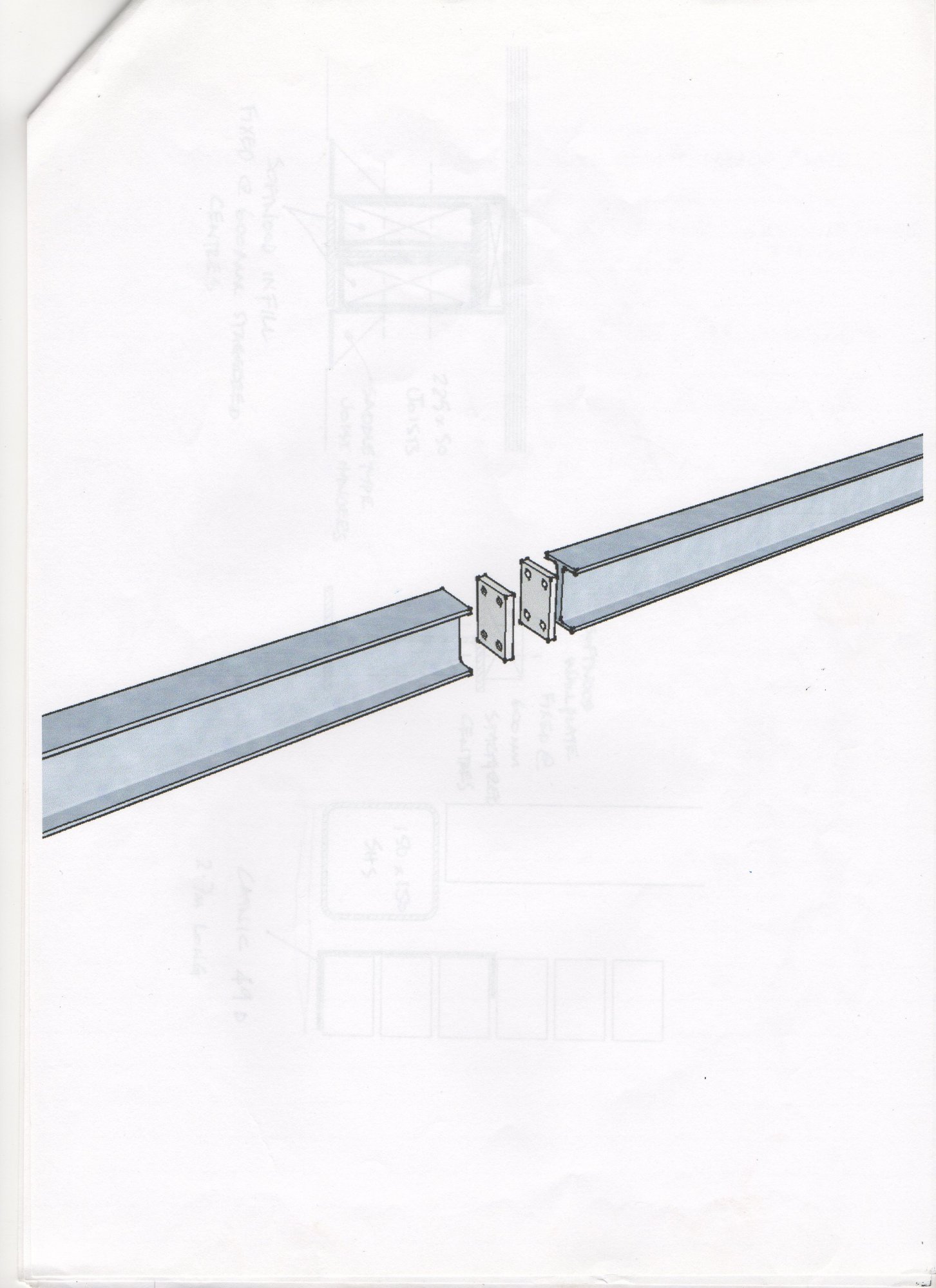
I am attempting to draw-up the steels myself, initially in sketchup, showing all the various tabs and stubby connection pieces to the tops of the posts to work out how it all goes together in detail, with a view to maybe then producing individual drgs for each steel and each pots, I would estimate there will need to be maybe ~15 unique drgs in total.
Should there be some drgs and should they have been produced by the architect or the engineer? or is it normal practice to just bundle what info I have to a steel fabricator and expect them to fathom it out (I assume not). I can't see how I can get quotes for the steels without some detailed drgs.
His drgs make reference to the steels needed and there is the usual (in my experience) scruffy hand written in 9B pencil, scanned, photocopied and issued (no checks or approvals signed) bunch of steel calcs and a few hand-drawn scratch/detail drgs showing a couple of the specific connections between members from the Engineer (that the architect commissioned, so a subby to him) and some crude and basic arrangement plan views within their pack to.
It's taken me a few hours to piece the steel calcs/drgs and the architect's drgs together to determine how it all goes together, although I'm still a bit unsure in some areas and I'm not convinced it all works yet.
Nowhere, between the two packs of info, are there drgs that would enable a steel fabricator to know what to fabricate, I'm talking dimensioned drgs for each piece of steel and the various posts, with each of the connections and tabs and holes and foot plates etc detailed on it and some sort of indication how each piece connects to another.
I am attempting to draw-up the steels myself, initially in sketchup, showing all the various tabs and stubby connection pieces to the tops of the posts to work out how it all goes together in detail, with a view to maybe then producing individual drgs for each steel and each pots, I would estimate there will need to be maybe ~15 unique drgs in total.
Should there be some drgs and should they have been produced by the architect or the engineer? or is it normal practice to just bundle what info I have to a steel fabricator and expect them to fathom it out (I assume not). I can't see how I can get quotes for the steels without some detailed drgs.