Cant find the old thread i started!
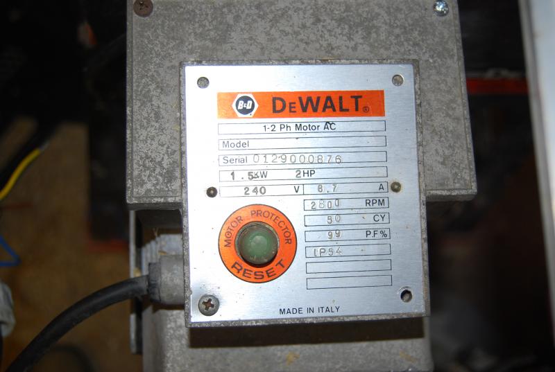
recently purchased an old dewalt planer thicknesser, which is 240volt. The guy who sold it to me said the capacitor needed replacing. Having opened it up i found he had also disconnected the wiring to the starter and a few bits were missing etc.
Ive replaced the capacitor and having wired it up to bypass the starter it does work. Ive now bought a replacement, but im a bit confused since it came with no wiring diagrams.
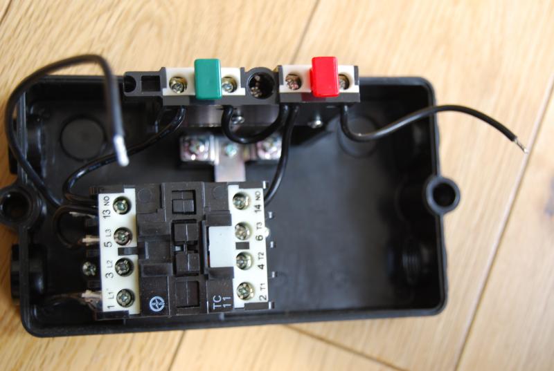
Basically i have a live neutral and earth from the suppl and likewise for the load going out. WHich goes where, and whats confusing me more is where do teh two black jumpers connect to? one comes from the terminal 13NO and the other comes from the red off button.
Ive seen a similar post on another site a few years old which appears to show a similar dol, but with a thermal overload relay in there as well. The jumper wires appear to go to that in the picture. The original dol didnt have one in it, but the box containing the capacitor does have a reset button.
So in short do i need a thermal overload relay, and if so, what size ampage do i need. If not, what do i do with the jumper wires?
many thanks for helping out a confused idiot.
recently purchased an old dewalt planer thicknesser, which is 240volt. The guy who sold it to me said the capacitor needed replacing. Having opened it up i found he had also disconnected the wiring to the starter and a few bits were missing etc.
Ive replaced the capacitor and having wired it up to bypass the starter it does work. Ive now bought a replacement, but im a bit confused since it came with no wiring diagrams.
Basically i have a live neutral and earth from the suppl and likewise for the load going out. WHich goes where, and whats confusing me more is where do teh two black jumpers connect to? one comes from the terminal 13NO and the other comes from the red off button.
Ive seen a similar post on another site a few years old which appears to show a similar dol, but with a thermal overload relay in there as well. The jumper wires appear to go to that in the picture. The original dol didnt have one in it, but the box containing the capacitor does have a reset button.
So in short do i need a thermal overload relay, and if so, what size ampage do i need. If not, what do i do with the jumper wires?
many thanks for helping out a confused idiot.
 it'll save you a headache and the cost shouldn't be eye-watering.
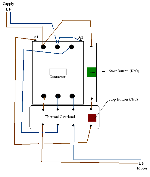
")