

Just wondering how to replace a honeywell bdr91 with a hive 2 receiver
The boiler i have is a viessmann vitodens 100
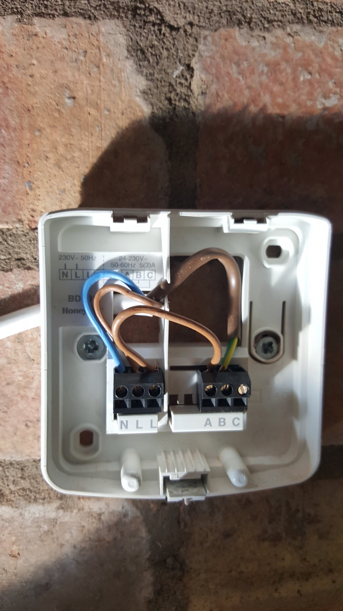
Heres my current honeywell wiring
Does anyone know what wires go where on the hive receiver from what ive found out from other forums the closest ive got is this
But im not 100% on this
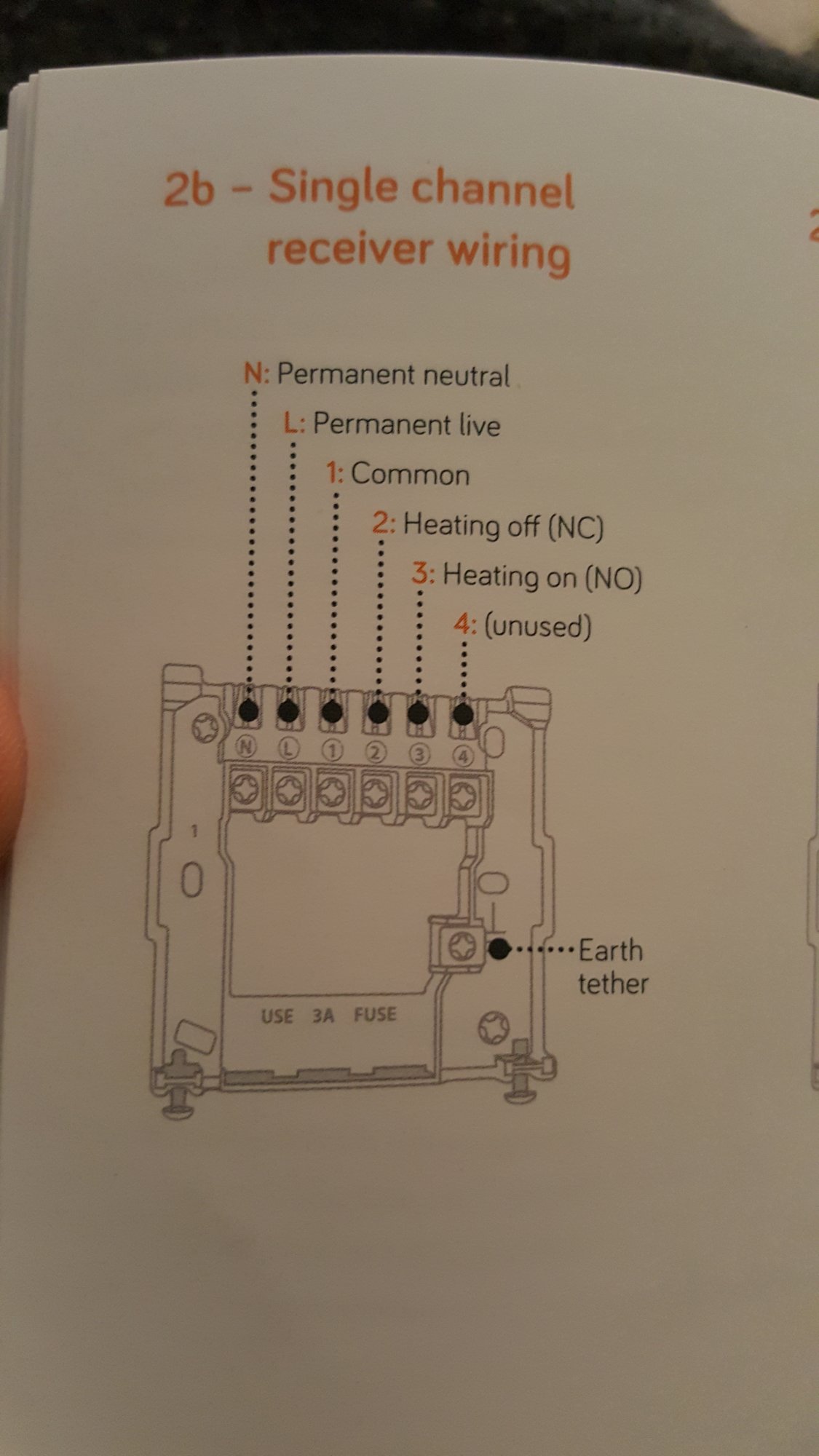
Heres the hive wiring diagram
The boiler i have is a viessmann vitodens 100
Heres my current honeywell wiring
Does anyone know what wires go where on the hive receiver from what ive found out from other forums the closest ive got is this
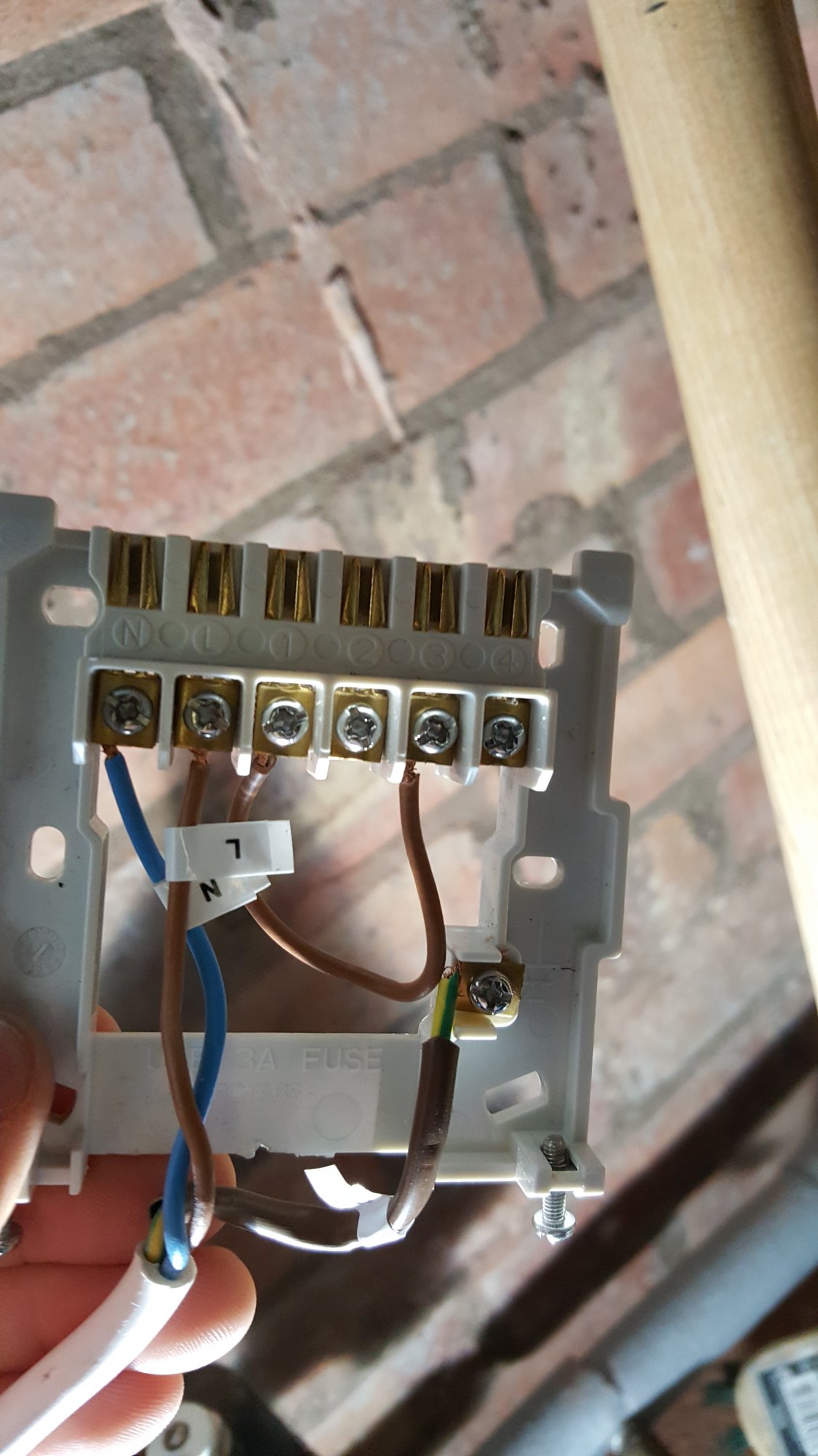
But im not 100% on this
Heres the hive wiring diagram
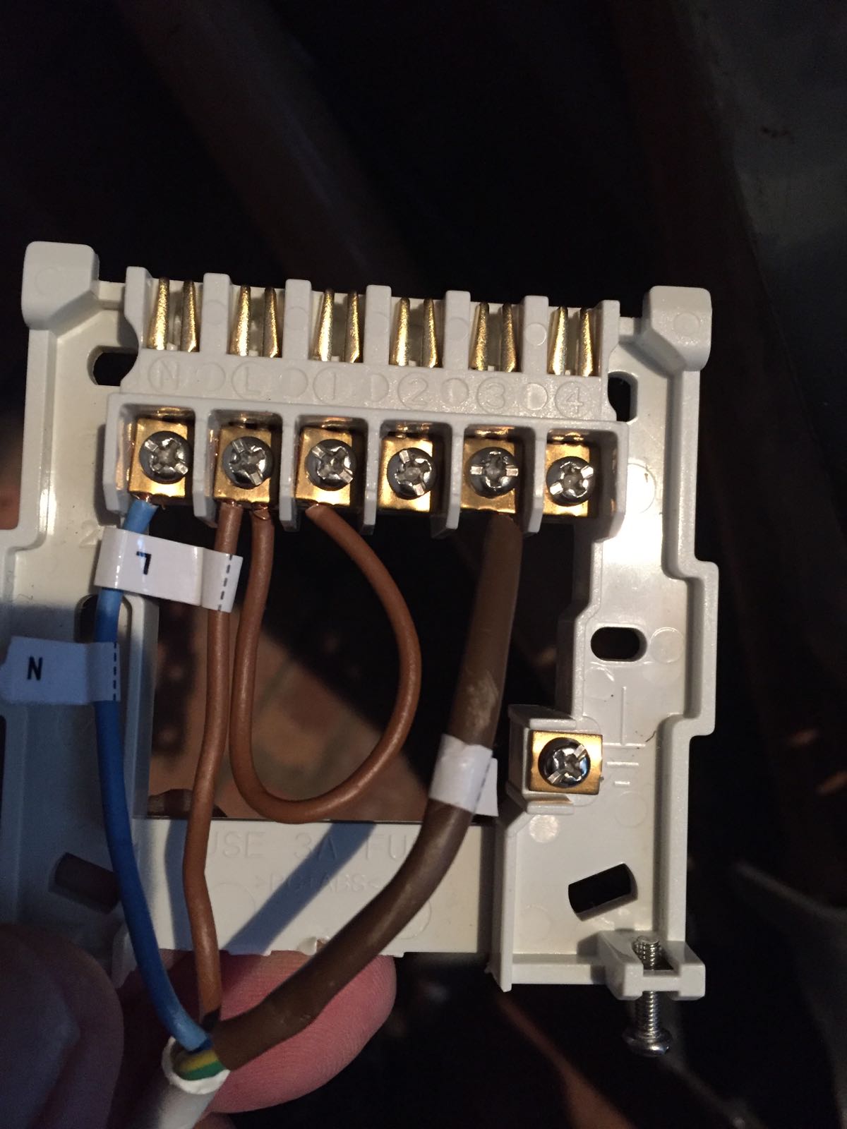
 There should not be very much, if any copper on show. There is a serious risk of those conductors touching each other. Make sure you sort that out when installing the Hive.