does balancing increase efficiency?

I've now measured the vertical drop between boiler and pump which is 2.4m. If I look at the Grundfos specs, a 2.4m head gives the following flow rates to the boiler:

Speed I = 0.75 m3/h
Speed II = 1.5 m3/h
Speed III = 2 m3/h

Does this mean the best setting to acheive the biggest drop at the boiler would be Speed I, giving 0.75m3/h or 12.5 L/min flow @ 12kW?

The CH just came on so I watched d.40 and d.41 as it heated up.. There was a 16C difference all the way upto the point where the boiler reached max temp (I'd upped d.5 to 58C to help with the DHW until I get the VRT392 which allows seperate temps). So when d.40 (flow) reached 58C, d.41 (return temp) was at 42C. d.41 then rose as the room stat approached the set temp (20C) to eventualy match d.40.

As a quick test, when flow was at 56C, I switched the pump to Speed I and withen a few seconds the boiler was 'eractically' modulating up / down (i.e. the symptoms micky suggested as not enough flow) so I switched it back after 30 seconds. So, I will stick with speed II at the pump as the minimum. (Thanks Micky for that valuable info!!)

Now would like to work out what my max difference could be with those flow rates?? (anyone know the calc?) ... Then see if I can achieve it! :)
 
Sponsored Links
I would take a bet my 'hand' does just as good a job as anything else you're using , quicker too. :p

I would probably agree, experience counts for a lot in 'measuring' by hand [I once had a job (a long time ago) where I'd often have to "bag up" 10lb of a product, after a while, I could guestimate 10lb to within 1-2oz every time from feel/sight:cool: ]

As I don't have that experience in heating, I'm having to use my technology instead! :)
 
d.41 then rose as the room stat approached the set temp (20C) to eventualy match d.40.
That sounds more like your TRVs cutting in than anything else. The temperature of the room being 10C or 20C wouldn't significantly affect the return temperature if all the radiators were still taking flow. Neither would any modulation that boiler might attempt. The only way the flow and return temperatures are the same is if there is no heat being lost on a trip round the system, either because the water is just whooshing through the pipes and not the radiators, or because it is taking a short cut through a bypass.

If the burners were cycled off then the flow and return temperatures would quickly match, but not at 58C. Maybe around 50C.
 
I've now measured the vertical drop between boiler and pump which is 2.4m. If I look at the Grundfos specs, a 2.4m head gives the following flow rates to the boiler:

Speed I = 0.75 m3/h
Speed II = 1.5 m3/h
Speed III = 2 m3/h
The head has nothing to do with the physical drop between the boiler and the pump. Saying that the head is X metres is just a way of saying what the pressure drop is around the circuit. It's the same as measuring atmospheric pressure. You can use different units: bar, kPA, mm Hg, ft of water.

The Grundfos literature shows the head in kPa as well as metres, which should ring bells to someone who is "technically minded". :rolleyes:

Read the second link I gave earlier.

As for balancing being a non-issue with the TRV4, I would rather accept the advice given by Drayton that it is important if you want them to work properly.
 
Sponsored Links
The head has nothing to do with the physical drop between the boiler and the pump. Saying that the head is X metres is just a way of saying what the pressure drop is around the circuit. It's the same as measuring atmospheric pressure. You can use different units: bar, kPA, mm Hg, ft of water.

The Grundfos literature shows the head in kPa as well as metres, which should ring bells to someone who is "technically minded". :rolleyes:

Read the second link I gave earlier.

:oops: Should have read that link earlier, it explains alot. Thanks!! :) I have many of the figures already, so I'll create a table as per the doc and see what it comes out with for my CH system! :) - I'll have to guess some of the joints and layout as they are sealed between the floor and ceiling.

The upstairs rad tails are all 15mm copper, the total rad output is 4.5kW, the downstairs are all 10mm drops with a total rad output of 5.5kW. Looking at your other link, as 10kW @ 1.5m/s is the max heat carrying capacity for 15mm copper, would it be "normal practice" for the primary circuit to therefore be 22mm feeding the rads? (The same as is being used to/from the pump/boiler)

Thanks again for the links, I've learn't something new as I had wrongly assumed the 'head' was related to physical height. :cool:

UpgradeMe
 
In every system with more than one circuit there will be a major, or index circuit.
The circuit with the highest resistance is the index circuit and this is usually the circuit with the longest run of pipes and/or the heaviest load.
It's importance lies in the fact that it is against the resistance of this circuit only that the pump duty has to be assessed, all other resistances being less than the index circuit resistance
But the pump head is applied to all circuits and so in all ircuits other than the index one extra resistance in the form of a a lockshield valve will need to be incorporated to proportion properly the flow of water in these circuits in relation to the heating loads they carry.
 
In every system with more than one circuit there will be a major, or index circuit.
... etc, etc.

... in all circuits other than the index one extra resistance in the form of a lockshield valve will need to be incorporated ...
I think the OP will have learnt this by reading the link I posted. :rolleyes:

In theory, the index rad does not need a LS valve. But, as it is virtually inevitable that the pump will be providing a greater head than is required, there will be a need for a LS valve on the last rad in the index circuit. If there is a considerable disparity between one circuit and another, it may be better to insert a balancing valve in the main pipe to the lower resistance circuit.
 
How do I calculate the maximum tempature rise from those figures? I'm not sure how you calculated the 8.6 l/min or the 13C rise?
You could use the specific heat capacity of water and work it out from first principles. I took the short cut and worked it from MI figures:

12.9 l/min * 12 kW / 18 kW = 8.6 l/min.

The volumetric heat capacity of water will be somewhere between 4.18 and 4.22 kJ/l/K - let's use 4.2.

12 kJ/s / 4.2 kJ/l/K / 20 K * 60 s/min = 8.57 l/min

Edit: I took the range of volumetric heat capacities from wikipedia, which suggested a higher volumetric heat capacity at 100°C than at 20°C, while keeping the same specific heat capacity, this sounds wrong. From http://www.simetric.co.uk/si_water.htm I get the densities of water at 4°C as 1 kg/l and 80°C as 0.9718. Using wikipedia's specific heat capacity of 4.1813 J/g/K, I make it that the volumetric heat capacity at 80°C would be 4.1813 * 0.9718 = 4.0634 J/cm³/K. Using this figure instead:

12 / 4.06 / 20 * 60 = 8.87 l/min at 80°C.

Anyway, the important thing is to limit the temperature rise across the heat exchanger to 20°C.
 
would it be "normal practice" for the primary circuit to therefore be 22mm feeding the rads? (The same as is being used to/from the pump/boiler)
Yes.

It's the "normal practice" because it means the installer does not have to bother calculating the actual flow rates and pressure drops and then sizing the pipes correctly. The drawback is that in some cases the pipes are so oversized that the flow rate is down at the "sludge" end, i.e below 0.3m/s. The other disadvantage is that it makes balancing harder.

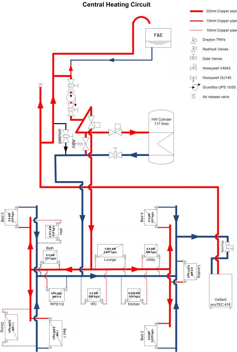
Okay. I've had a look around and I *think* the below pic is roughly the design / layout. Does this "H" shape feeding the rads look like it would work? The return feed to the boiler from the "H" and Cyl is possibly not linked in the correct place, it's hard to guess from what I can see.


If it looks about right, I can easily measure the pipes (roughly) and fill in the table to calculate the head! :)
 
From http://www.simetric.co.uk/si_water.htm I get the densities of water at 4°C as 1 kg/l and 80°C as 0.9718. Using wikipedia's specific heat capacity of 4.1813 J/g/K, I make it that the volumetric heat capacity at 80°C would be 4.1813 * 0.9718 = 4.0634 J/cm³/K.
But see Thermal properties of water
So at 80°C the volumetric heat capacity of water would be 0.9718 * 4.198 = 4.080

Probably best to use roughly 4.1 kJ/l/K for boiler flow calcs. (Better than 4.18 or 4.2)

Okay.... all these measurement units are new to me, but I'm getting there. How did you calculate the maximum tempature rise to be 13C @ 12l/s? i.e. what would the calc be to determine the maximum difference I could achieve at a given flow rate?
 
The assumption is that the boiler flow rate is set according to MI. Then the temperature rise is directly proportional to boiler output. The manual states 18 kW at 12.9 l/min gives a temperature rise of 20°C. Keeping the flow rate constant, 12 kW gives a temperature rise of 20°C × 12 kW ÷ 18 kW = 13°C.

Using different flow rates, you can calculate the temperature rise across the boiler as:

ΔT (K) = power (kW) ÷ flow (l/min) ÷ 4.1 (kJ/l/K) × 60 (s/min)
 
Okay. I've had a look around and I *think* the below pic is roughly the design / layout.

I can see one glaring error to start with. The return from the hot water cylinder must be the last tee before the boiler; it must come after all radiator return tees. As drawn the lounge, kitchen, utility, bed 2 and bed 4 all have their returns connected after the cylinder return.

The reason for connecting the cylinder return last is to prevent reverse circulation. This can happen when the heating valves are closed and the HW one is open. Water travelling down the return pipe from the cylinder will get diverted up the return pipes to the rads, thus heating them up. This would be noticeable in the summer when the rads, which are supposed to be off, feel warm.

Have you checked that the 10mm drops are actually off the main pipe and not fed from a central manifold?
 

DIYnot Local

Staff member

If you need to find a tradesperson to get your job done, please try our local search below, or if you are doing it yourself you can find suppliers local to you.

Select the supplier or trade you require, enter your location to begin your search.


Are you a trade or supplier? You can create your listing free at DIYnot Local

 
Sponsored Links
Back
Top