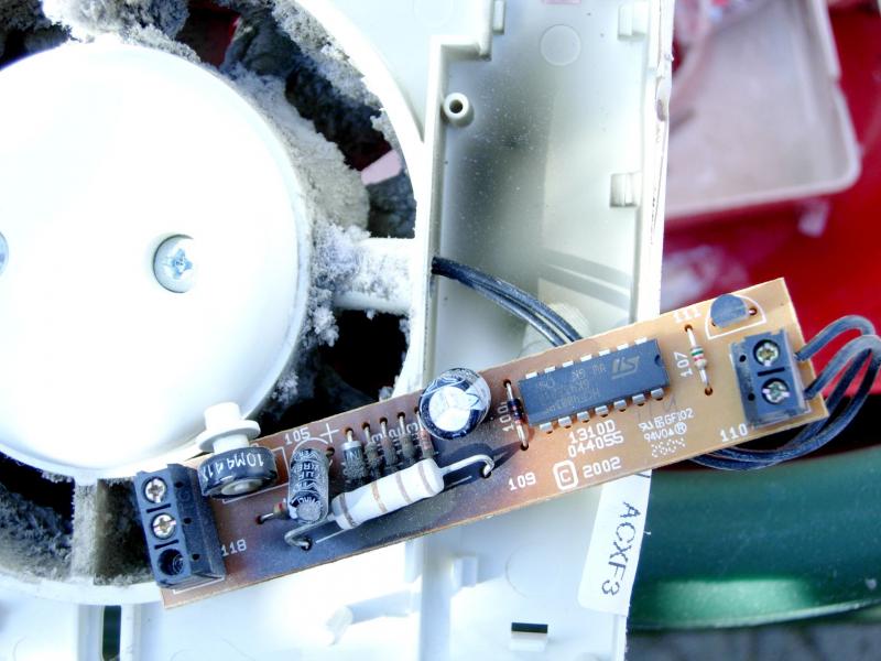
For many years, almost every small timer fan I’ve dissected has had essentially the same means of deriving power for the timer electronics – a dropping resistor (usually 22kΩ or 24kΩ, looking about 2W rating), rectifier diode and 15V zener diode (with capacitor) in series between L & N. By my reckoning, that amounts to a constant load of about 1.12W (at 240V, which is what most of us have), whether or not the fan is operating (for those interested in such things, approaching an ‘energy wastage’ of 10kWh per year).
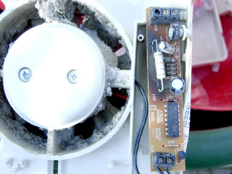
Virtually every such fan I have taken out of service has shown appreciable thermal damage resulting from the heat dissipated in the dropping resistor – always appreciable heat damage to the resistor itself, usually associated with varying degrees (sometimes very marked) of thermal damage to the PCB and nearby components. In the last one I replaced, there was marked scorching of much of the PCB and the resistor had got so hot that it had unsoldered the joints at both ends.
The resistance of the dropping resistors is always still roughly ‘in-spec’ when removed, so what we are seeing must be the consequence of the normal/intended (about 1.12W) dissipation in the resistor (maybe a bit less, since it gets so hot), not any sort of overload or fault.
Does this correspond to other people’s experiences? Do these things ever actually catch on fire? It’s tempting to suggest, from my experiences, that the design is not really ‘fit for purpose’ – although, without considerably increasing the complexity (hence cost, and probably space requirements) it’s difficult to see what else they could do. I’m not sure that increasing the power rating of the dropping resistor (even if a bigger one would fit) would achieve very much, since the same amount of power would still be dissipated, and the problem is more one of cooling/air circulation than of the actual rating of the component (I've never seen one which has actually 'died'). One might consider routing a tiny bit of the fan’s airflow for ‘cooling’ purposes – but, since that would only work when the fan was operating, would probably not help very much in terms of the big picture.
Any observations/thoughts?
Kind Regards, John.