
- Joined
- 22 Mar 2014
- Messages
- 9
- Reaction score
- 0
- Country

Am looking to extend my ring main by 4 sockets from a socket that is no longer required (at its present location) and wanted to check if the following solution (using materials I have to hand) meets all the required regulations.
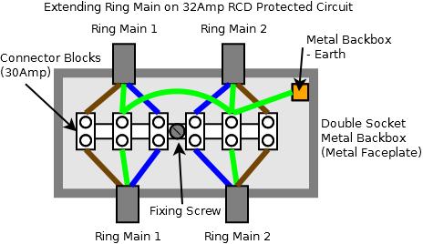
I've attached a diagram of a double socket metal back box that I would like to fill with 6 30amp connector blocks. The ring circuit is on a 32amp rcd protected circuit. I will be placing a blanking plate over it.
Would this approach meet regulations and the approval of your helpful sparky selves?
Thanks
") ). From an electricians point of view are there tests this will interfere with?
). From an electricians point of view are there tests this will interfere with?