
You are using an out of date browser. It may not display this or other websites correctly.
You should upgrade or use an alternative browser.
You should upgrade or use an alternative browser.
Does this need certifying and why?
- Thread starter samohtom
- Start date
Hi. Thanks for replies! The reply I got from LABC on querying my interpretation of the changes to part P was:-
I agree with the interpretation of the current requirements of the building regulations as set out in the "changes to Part P" leaflet that you have provided.
Therefore, provided that the work that you propose is in line with the exemptions there will be no need to notify building control of the works.
Please note that regardless as to whether the work is notifiable or not the work should still be carried out in strict accordance with BS7671. Therefore testing, routing, protection and certification etc. should all be adhered to and undertaken although not necessarily notified.
---------------
My inclination at this point is to get myself something like a good quality plug in tester that does a basic earth loop impedance test and polarity test as well (maybe a Sok36 or martindale EZ150). Found this form to use:-
https://www.elecsa.co.uk/Documents/.../BS7671-Amd1-Minor-Works-Certificate-(1).aspx
With my multimeter I could do R1+R2, R2, continuity. The plug in tester would do earth loop impedance (albeit not with a specific reading) and test the polarity. An insulation resistance meter can be had off ebay for <£20. Only thing left is RCD, I'd just push the button! Again not exactly how it's meant to be done, but adequate? Lowest firm quote so far has been £120...so I'm thinking save myself some cash and get a meter I can regularly check for faults with myself.
Thoughts?
My experiance has been that most multimeters* can't measure resistances accurately enough to give meaningful R1+R2 figures.
Still even determining that things are in the right ballpark is a lot better than what most DIYers do which is not testing at all.
* When I was a phd student I had one in my office that could do resistances that low with reasonable accuracy but that was a rather exepensive agilent bench meter.
Still even determining that things are in the right ballpark is a lot better than what most DIYers do which is not testing at all.
* When I was a phd student I had one in my office that could do resistances that low with reasonable accuracy but that was a rather exepensive agilent bench meter.
Hi. I had a local electrician come take a look - he thought my work looked like it met regs, but because it had a lot of joins (I used Wago's instead of twisting cables etc) he wasn't happy to certify it in case NICEIC picked my job later to make him break it down. He did however be incredibly generous and lend me all his instruments over this weekend  So I've done it myself.
I doubt that shout out's to particular companies are allowed on the forum, but if they were he'd be getting one, how many guys would just lend their kit to someone they only just met?
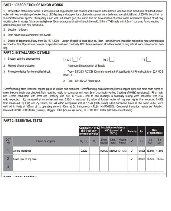
With regards to RCD disconnect times, I measured at the furthest outlet on the ring and quoted the higher 180 degree phase figures (I didn't know whether it's supposed to be quoted at 0 or 180 so went with the highest). If anyone knows why 180 degree phase figures are a bit higher, I'd be interested to know (being a layman, I've no idea).
So I've done it myself.I doubt that shout out's to particular companies are allowed on the forum, but if they were he'd be getting one, how many guys would just lend their kit to someone they only just met?
With regards to RCD disconnect times, I measured at the furthest outlet on the ring and quoted the higher 180 degree phase figures (I didn't know whether it's supposed to be quoted at 0 or 180 so went with the highest). If anyone knows why 180 degree phase figures are a bit higher, I'd be interested to know (being a layman, I've no idea).
Twisting is/was never acceptable.(I used Wago's instead of twisting cables etc)
The RCD should be tested at the consumer unit with loads disconnected.With regards to RCD disconnect times, I measured at the furthest outlet on the ring
The higher figure of each test is recorded.and quoted the higher 180 degree phase figures (I didn't know whether it's supposed to be quoted at 0 or 180 so went with the highest).
The maximum allowed at 1x is 300ms.
There are other mistakes on your certificate which has disappeared.
It depends at which point in the cycle you start the test.If anyone knows why 180 degree phase figures are a bit higher, I'd be interested to know (being a layman, I've no idea).
Certificate:
Part 2
3. Protective devices
1. Type - The MCB protecting the ring, BSxxxx 30/32A?
2. Type - The fuse in the FCU, BS1362 3A?
There is no need for any of your text but -
"Looks like 6mm²" isn't really good enough,
Re: measured Zs - Megger no-trip readings are notoriously unreliable - get a Fluke. Use the added figures of Ze and R1+R2.
As above - 1x limit 300 ms.
Part 3
It's not a Ring main (they are in the road); it's an A1 Ring Final Circuit.
You have not recorded R2 nor IR for the spur.
The Zs of the spur is half that of the ring ???
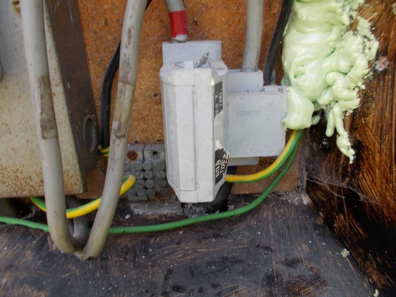
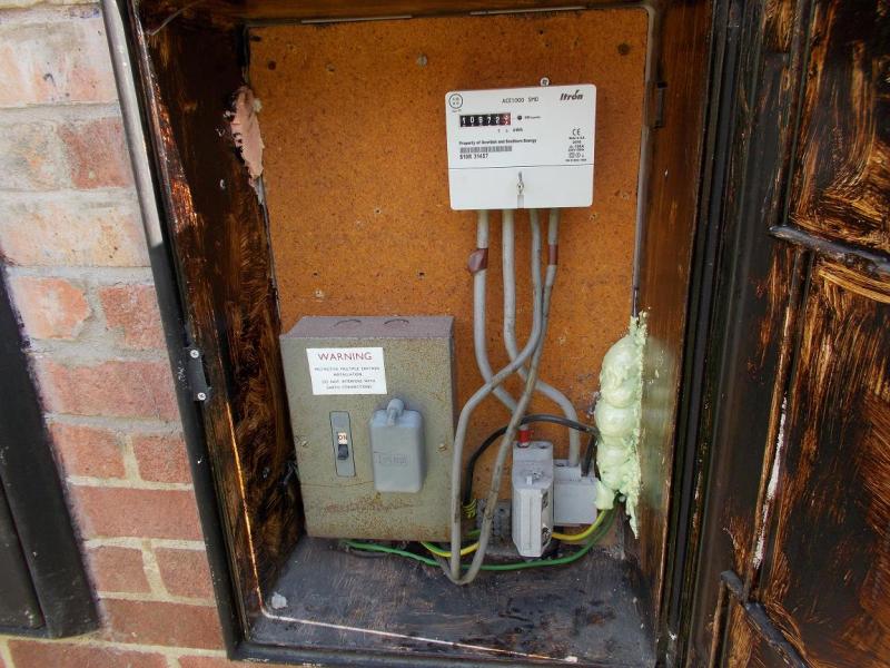
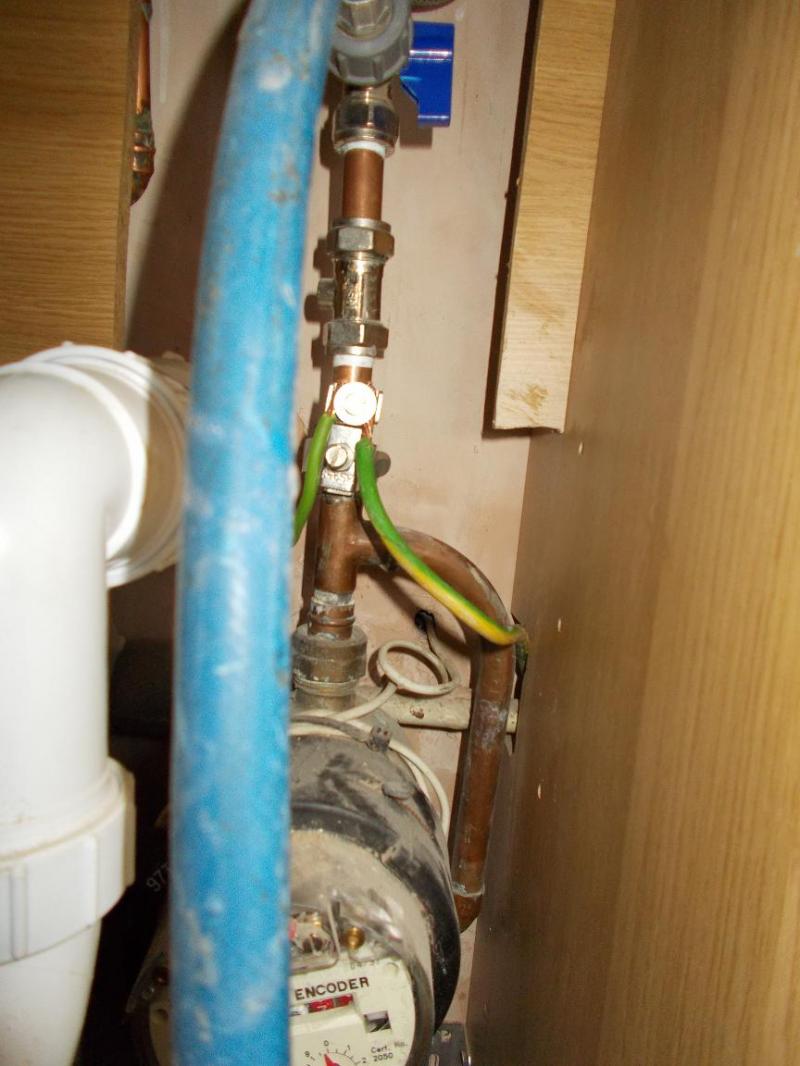
Thanks for the replies. I took the previous version of the minor works down as I realised a few things were wrong. The hawk eyed among you obviously spotted it too quickly! I wonder if anyone can please identify the size of the green/yellow bonding cable (pics show this at the meter box and the other end attached to pipework under the sink) and the smaller green earthing cable in the meter box? I'm assuming the green/yellow sticker on the neutral lead means it's been used a return earth? The slimmer green earthing cable goes straight through my meter box and terminates in my upstairs neighbours meter box earthing terminal. I took a reading of the resistance between the consumer unit end and the end at this meter box and it was 0.18 Ohms - does this sound acceptable? The resistance for the larger bonding cable to the kitchen came out 1.48 Ohms (probably in the regions of 10-15m of cable).
Regarding the Zs value, I took this at the furthest outlet on the ring circuit. I actually went round and measured it at every outlet - that for the new double socket the fused spur is taken off (which is very close to the consumer unit just the other side of the kitchen wall) came in as 0.27 Ohms. The Zs values increased the further I got from the consumer unit in quite a consistent fashion to give the maximum 0.62 Ohms at the furthest outlet. Not a lot I can do about remeasuring RCD times as the kits gone back, I think I thought measure at the furthest outlet on the ring because that's the furthest distance the current has to travel to trip the RCD. Still, I measured the times at all the outlets on the ring and they were all well within limits (and very similar values), so I'm happy that it's working as it should. One thing I did find - the lights and immersion are only on an MCB, not an RCD and MCB. I suspect if I got a PIR done professionally they'd say do something about that.
Regarding the Zs value, I took this at the furthest outlet on the ring circuit. I actually went round and measured it at every outlet - that for the new double socket the fused spur is taken off (which is very close to the consumer unit just the other side of the kitchen wall) came in as 0.27 Ohms. The Zs values increased the further I got from the consumer unit in quite a consistent fashion to give the maximum 0.62 Ohms at the furthest outlet. Not a lot I can do about remeasuring RCD times as the kits gone back, I think I thought measure at the furthest outlet on the ring because that's the furthest distance the current has to travel to trip the RCD. Still, I measured the times at all the outlets on the ring and they were all well within limits (and very similar values), so I'm happy that it's working as it should. One thing I did find - the lights and immersion are only on an MCB, not an RCD and MCB. I suspect if I got a PIR done professionally they'd say do something about that.
- Joined
- 11 Jan 2004
- Messages
- 46,732
- Reaction score
- 3,930
- Country

The resistance for the larger bonding cable to the kitchen came out 1.48 Ohms (probably in the regions of 10-15m of cable).
Bonding conductors should measure out at 0.05 Ohms or less.
That is wrong - it's far too high. Assuming it's 10mm wire, actual resistance should be around 0.02 ohmsThe resistance for the larger bonding cable to the kitchen came out 1.48 Ohms (probably in the regions of 10-15m of cable).
Even if it was tiny 1mm wire, your value is still massively more than it should be.
On a ring circuit, the Zs value should be the same at every outlet.The Zs values increased the further I got from the consumer unit in quite a consistent fashion to give the maximum 0.62 Ohms at the furthest outlet.
Increasing as you get further away from the origin indicates it is a radial, or a ring which has been broken somewhere. If the protective device for the circuit was selected as if it would be a ring, it will now be the wrong one.
- Joined
- 11 Jan 2004
- Messages
- 46,732
- Reaction score
- 3,930
- Country
As regards the ring final, what were the end to end results?
Thanks for the replies. I took the previous version of the minor works down as I realised a few things were wrong. The hawk eyed among you obviously spotted it too quickly!
")
I can't really tell.I wonder if anyone can please identify the size of the green/yellow bonding cable (pics show this at the meter box and the other end attached to pipework under the sink) and the smaller green earthing cable in the meter box?
If you can bend it with the fingers of one hand then it is likely to be 6.
Can you tell using this? http://www.diynot.com/wiki/Electrics:flatpvccables
Just because it is black does not mean you can call it a neutral lead.I'm assuming the green/yellow sticker on the neutral lead means it's been used a return earth?
It does appear to be an earthing conductor.
Please confirm that it is connected to the cut-out as there is a black cable below and behind which looks like a continuation.
If that one is 6mm² then the others must be 10mm².The slimmer green earthing cable goes straight through my meter box and terminates in my upstairs neighbours meter box earthing terminal.
No, they should be negligible, <0.05Ω.I took a reading of the resistance between the consumer unit end and the end at this meter box and it was 0.18 Ohms - does this sound acceptable? The resistance for the larger bonding cable to the kitchen came out 1.48 Ohms (probably in the regions of 10-15m of cable).
Did you deduct the resistance of your leads?
You could recheck this with a multimeter.
I would suspect the meter.Regarding the Zs value, I took this at the furthest outlet on the ring circuit. I actually went round and measured it at every outlet - that for the new double socket the fused spur is taken off (which is very close to the consumer unit just the other side of the kitchen wall) came in as 0.27 Ohms. The Zs values increased the further I got from the consumer unit in quite a consistent fashion to give the maximum 0.62 Ohms at the furthest outlet.
If your end-to-end measurements are as they should be then there isn't much you can do.
Yes, that sounds fine but there may be things on the circuit which could affect the times and it is the actual device that you are testing.Not a lot I can do about remeasuring RCD times as the kits gone back, I think I thought measure at the furthest outlet on the ring because that's the furthest distance the current has to travel to trip the RCD. Still, I measured the times at all the outlets on the ring and they were all well within limits (and very similar values), so I'm happy that it's working as it should.
They would comment on it but it is fine.One thing I did find - the lights and immersion are only on an MCB, not an RCD and MCB. I suspect if I got a PIR done professionally they'd say do something about that.
End to end measurements were:-
N-N 0.35 Ohms
L-L 0.34 Ohms
E-E 0.91 Ohms
which fits with the old 2.5mm T+E with 1mm CPC, so ratio of 1:2.5. Definitely no broken ring.
I now suspect I hadn't auto-nulled the leads, at least for the kitchen one. Because of the distance to the meter box from the consumer unit, I had to use some very thin wire (model railway wire off ebay, probably <0.5mm csa - I can hear the laughter now ). In hindsight I think this caused the high resistance with the bonding to the kitchen and I hadn't auto nulled it. For the earthing though, I do think it was auto nulled. I think the problem may be linked to using this wire I shouldn't have as I did an earlier reading for the earthing cable to the meter box (and somehow managed to stretch it so I it reached without needing anything else) and got 0.03 Ohms which sounds like what I should have. I have a basic multimeter, I'll recheck at some point soon.
The black lead with yellow/green tape on is just connected to the earthing terminal. The other bit of yellow/green cable below the tape in the picture goes from this terminal to somewhere inside the metal box on the left (it goes in underneath). Thanks for the link on cable sizes - I've measured the bundle of strands and I'm now pretty sure they're 6mm earthing and 10mm bonding (I tried the bend it with your fingers thing too, good tip!)
For the Zs going round the ring I values from 0.27 Ohms to 0.62 Ohms closest to furthest and varying values in between. End to end seem ok though...maybe it's not the best meter? Would a loose connection to the socket outlet cause a higher reading?
I didn't mention that I did actually unplug literally everything before testing the circuit, so there shouldn't be any extra loads on the RCDs affecting those times.
N-N 0.35 Ohms
L-L 0.34 Ohms
E-E 0.91 Ohms
which fits with the old 2.5mm T+E with 1mm CPC, so ratio of 1:2.5. Definitely no broken ring.
I now suspect I hadn't auto-nulled the leads, at least for the kitchen one. Because of the distance to the meter box from the consumer unit, I had to use some very thin wire (model railway wire off ebay, probably <0.5mm csa - I can hear the laughter now
). In hindsight I think this caused the high resistance with the bonding to the kitchen and I hadn't auto nulled it. For the earthing though, I do think it was auto nulled. I think the problem may be linked to using this wire I shouldn't have as I did an earlier reading for the earthing cable to the meter box (and somehow managed to stretch it so I it reached without needing anything else) and got 0.03 Ohms which sounds like what I should have. I have a basic multimeter, I'll recheck at some point soon.The black lead with yellow/green tape on is just connected to the earthing terminal. The other bit of yellow/green cable below the tape in the picture goes from this terminal to somewhere inside the metal box on the left (it goes in underneath). Thanks for the link on cable sizes - I've measured the bundle of strands and I'm now pretty sure they're 6mm earthing and 10mm bonding (I tried the bend it with your fingers thing too, good tip!)
For the Zs going round the ring I values from 0.27 Ohms to 0.62 Ohms closest to furthest and varying values in between. End to end seem ok though...maybe it's not the best meter? Would a loose connection to the socket outlet cause a higher reading?
I didn't mention that I did actually unplug literally everything before testing the circuit, so there shouldn't be any extra loads on the RCDs affecting those times.
That couldn't possibly be true. One socket could be right next to the CU, with an (R1+R2) of virtually zero, whilst another might be in the middle of a 100m long ring, hence with an (R1+R2) corresponding to two 50m long cables in parallel (i.e. fairly 'high'). Zs is obviously just (R1+R2) plus Ze.On a ring circuit, the Zs value should be the same at every outlet.
With a ring, (R1+R2) increases (along both 'arms') non-linearly from zero at the CU to a maximum at the middle of the ring (see illustrative graph below). With an unbranching radial, (R1+R2) will increase linearly from CU to the far end. Again, Zs is obviously just (R1+R2) plus Ze.Increasing as you get further away from the origin indicates it is a radial, or a ring which has been broken somewhere.
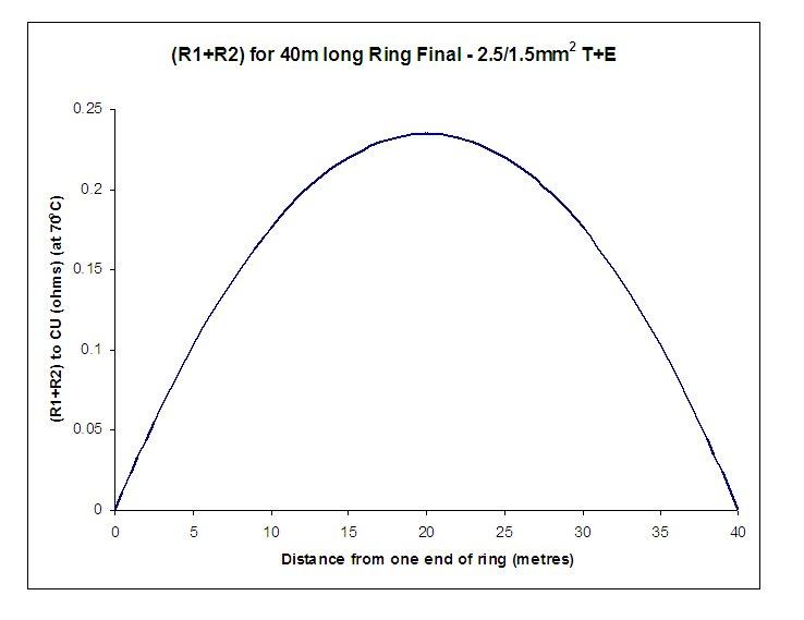
Kind Regards, John
It isn't, clearly a mistake.That couldn't possibly be true.On a ring circuit, the Zs value should be the same at every outlet.
I was thinking of the other tests done on rings where the ends are linked together first.
sounds like my Zs values were behaving as expected.....great 
I recorded PFC values as I went round doing the Zs ones too. They did the reverse and got smaller the further from the consumer unit I got....closest socket gave 0.85kA/850Amps, furthest one 0.37kA/370 Amps. Are these values ok? I've posted my updated cert below:-
Thanks
I recorded PFC values as I went round doing the Zs ones too. They did the reverse and got smaller the further from the consumer unit I got....closest socket gave 0.85kA/850Amps, furthest one 0.37kA/370 Amps. Are these values ok? I've posted my updated cert below:-
Thanks
DIYnot Local
Staff member
If you need to find a tradesperson to get your job done, please try our local search below, or if you are doing it yourself you can find suppliers local to you.
Select the supplier or trade you require, enter your location to begin your search.
Please select a service and enter a location to continue...
Are you a trade or supplier? You can create your listing free at DIYnot Local
Similar threads
- Replies
- 10
- Views
- 538
N
- Replies
- 58
- Views
- 9K