Sub-Board - Second Consumer Unit

Pot luck? Surely there’s a science to it?
Well, it's all science, but not science that we can necessarily utilise, since we do not know all the factors concerned - in particular the inevitable small variations in behaviour between items coming off a production line, and what 'ageing' has happened to the devices since they were put into service.
I guess the basic requirement is that the cable and mcb can take the load applied to it under normal working circumstances.
Indeed. The cable should be chosen to be adequate for the load, and then the MCB chosen so as to given adequate protection to that cable.
I’m not on a smart meter but is there a way to “measure” current usage in amps?
It's hardly an answer, but in order to measure current, you need some sort of current-measuring device!

Kind Regards, John
 
Sponsored Links
Pot luck? Surely there’s a science to it?
As explained, yes there is a science to it - but there is information missing which would be needed to say what is likely to happen.
For descrimination to make one MCB trip but the other not trip, as John said, the fault current would need to be above that needed to trip the smaller MCB, but below that needed to trip the higher rated one. Typically for at least one of the devices, the fault current will be in the area on the graph that ye old worlde cartographers would have labelled "here be dragons". So we have undocumented characteristics, variations in both tripping characteristics and mechanical operations, and it all adds up to there being a lot of uncertainty.
I guess the basic requirement is that the cable and mcb can take the load applied to it under normal working circumstances.
Correct. The MCB in your main board will be chosen to protect the cable as far as the second board. The MCBs in your second board will be chosen to protect the cables in the circuits attached to them.
I’m not on a smart meter
If you do a search, you'll find that many of us consider that a good thing ;)
but is there a way to “measure” current usage in amps?
Many ways !
There are many (so called) energy monitors which come with a clip on current sensor that you simply clip around one of your meter tails - the only thing these type can tell you is the current. Some also plug into a socket and can measure both voltage and phase angle - giving you real power values. And then there are the plug-in types where you can measure the consumption of individual items of (plug in) equipment.
Some of us have clip-on ammeters (as a piece of test equipment) where you just pop the jaws around a cable and it reads the current flowing.
 
Oh yes, as an example of the vagaries of discrimination ...
I was troubleshooting the boiler at the church - supply from a B6 MCB (plug in in an old Wylex fuseboard upstairs in the tower) and then a 3A fuse in an FCU down in the boileroom round the back. On switching on the FCU in the boiler room, "nothing seemed to happen". Checked fuse and it was OK, checked voltage on terminals and found no supply - this is how I found out which MCB it was supplied from ! On switching on the MCB, I heard the pump momentarily spin up and then stop - and the MCB stayed closed. On checking, the 3A fuse had blown.
During the course of fault finding, this cycle repeated several times - first time MCB would trip but fuse not blow, on resetting MCB the fuse would blow. My best guess on this is that the MCB goes through a "doesn't trip properly" position while switching it on. I can't remember whether I did any tests resetting the MCB while the FCU was switched off.
For good measure, there's also another FCU on the board that the supply goes through - my guess (not looked in it) is that it has a 13A fuse in since that hasn't blown.
Eventually I tracked it down to a faulty frost stat. This seemed to give an OKish IR reading at 500V with my MFT, but shorted internally when fed with mains.
 
Sponsored Links
One might 'wonder', but, as a general comment, I don't think one could actually determine by calculation whether one was likely to get discrimination between a particular pair of MCBs unless (a) one had curves indicating actual (typical) disconnection times with currents considerably greater than (for a Type B) 5In (for the lower-rated MCB) and (b) a specification which indicated the duration of a current >5In (for Type B) below which it must not operate (for the higher-rated MCB). I don't think that the former are freely (if at all) available, and I don't think the latter is included in the spec of an MCB.
Indeed.

I wasn't suggesting that the upstream device would necessarily be an MCB:

Just a thought - if you're supplying a CU with B32s in it, what upstream device do you need to get selectivity?

There is a reason why it's often recommended to use a cartridge fuse as the upstream OPD. There's a distinct difference in tripping curves which is likely to give discrimination.
Indeed.

So given that overload protection of the sub-main cable cannot be provided by the aggregation of MCBs in the CU it supplies, do we know that the electrician did not choose an upstream device which would give selectivity and that its In meant using 16mm²?
 
Whilst I admit that I talked in term of two MCBs, the issue I was talking about applies equally no matter what the nature of the upstream OPD.
 
Soooo .... I headed the advice on here and just got the spark in to run the cables. I helped him get boards up etc but as directed let him design and choose the route for the 16mm cable.

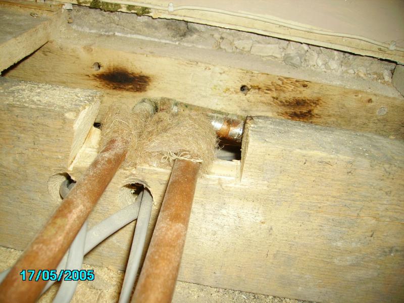
It’s a 25m run but aboit half way he’s poked through a hole and run the cable aside some heating pipes. Looking at the run he didn’t have any other options short of taking a ceiling down.

So I’ve got a 6inch section touching / right next to the heating pipes.

Your thoughts please gents (and ladies if we have any).
 
Also, what temperature do you run the heating at ? Older systems regularly ran at 70˚C or higher - and that's the temperature rating of the cable IIRC :eek: If yours run at a lower temperature then that's better.
As to insulation, well it's a matter of what you can get in. Ideally some insulation foam, but it comes down to what you can get in there without putting a lot of pressure on the cable - just a couple of mm will help, especially if the cable is then against the joist through the hole (the joist will act as something of a heatsink for it).
 
It crosses the flow pipe on the right as it turns the corner. In the next room

Unfortunately that’s right under a small staircase so I can’t get to it.

Looking in total it probably crosses about an inch...

Flow / return in red
Gaz in yellow
 

Attachments

  • 9C3B01E1-A1AA-4F5D-8CED-850D47C32178.jpeg
    9C3B01E1-A1AA-4F5D-8CED-850D47C32178.jpeg
    265.3 KB · Views: 82

DIYnot Local

Staff member

If you need to find a tradesperson to get your job done, please try our local search below, or if you are doing it yourself you can find suppliers local to you.

Select the supplier or trade you require, enter your location to begin your search.


Are you a trade or supplier? You can create your listing free at DIYnot Local

 
Sponsored Links
Back
Top