Hi all,
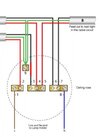
I'm looking for some pointers in finding a fault in a ceiling light at the top of my stairs. There are 2 switches + an intermediate switch (bottom of the stairs, top of the stairs & hallway). I tested with a voltmeter at all switches and the light itself and there's no power.
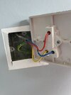
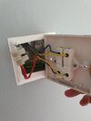
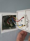
Any advice where to start? Fuses on the consumer unit are all fine. The switch at the top of the stairs has 2 cores connected in a terminal block, would that be where the power should be fed into the circuit? Should i just be trying to trace that cable to check the source?
It's the only light that doesn't work upstairs. Just moved in the house a couple of months ago and it's never worked.
Cheers
I'm looking for some pointers in finding a fault in a ceiling light at the top of my stairs. There are 2 switches + an intermediate switch (bottom of the stairs, top of the stairs & hallway). I tested with a voltmeter at all switches and the light itself and there's no power.
Any advice where to start? Fuses on the consumer unit are all fine. The switch at the top of the stairs has 2 cores connected in a terminal block, would that be where the power should be fed into the circuit? Should i just be trying to trace that cable to check the source?
It's the only light that doesn't work upstairs. Just moved in the house a couple of months ago and it's never worked.
Cheers