Honeywell ST699 to ST9400C Wiring Issues

Joined
15 Jan 2023
Messages
11
Reaction score
0
Country
United Kingdom
Afternoon all, I'm hoping someone can help here as we are now without heating!

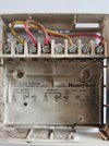
Bit of background - I had a ST699 programmer controlling our heating and hot water. It has worked flawlessly for 20 odd years, but last year, it started playing up. First thing that happened was that we couldn't have the heating and water on at the same time. Then, just before Xmas, it started to switch off (the display disappeared) and either the heating or hot water just went off. If I switched off the power and then switched it back on again, it would fire back up. It's hit and miss as to how often this happens. I googled the direct replacement (after looking at the cost of a ST699) and the advice from Honeywell was the ST9400C, so I bought one.

The wiring "swap" looked pretty straight forward in the instructions, so I went ahead and did it.

It's all connected and I've set the time and date, all is okay. However, even though the lights come on, it won't fire up either the heating or the water!

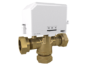
I have an old set up of boiler and hot water tank, no thermostat.

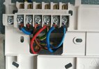
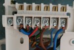
When it didn't work, I've Googled again and come across this Forum. Whilst I can find a few issues other users have had, I can't find anything that relates to my issue. I have noticed however, that the old wiring to the ST699 that is redundant, wasn't as per the diagram I saw in one of the posts. I have cables linking:

7 ---> 3
6 ---> 5
5 ---> Live

Whereas the post I saw suggested linking cables were between 8, 5 & Live?

Am I missing something? Do I have a faulty unit? Any help greatly appreciated.
 
Sponsored Links
Can you please provide a picture of the ST9400 wiring. Do you also have any pictures of the prior ST699 wiring to compare. If you don't have a picture of the ST699 wiring can you carefully outline the connections on the ST699 (terminal, wire colour, etc) and to which terminals they were moved for the ST9400. You said "I have cables linking:" did you mean "I HAD cables linking.. on the ST699".

On the ST9400 you should only have connections to (S-plan or y-plan systems only)

N & L (power)
3 : Hot Water on
4 : Central Heating on

and 1 (HW off) if you have a Y-PLAN system.

plus the earth tether if appropriate.

Generally there should be no links between any terminals on the ST9400.

That said based on your prior ST699 wiring. I think your hot water was permantly on as you had linked L->5->6 . And the HW-OFF (7) was linked to CH-ON (3).

If you can confirm, the required connections on the ST9400 should be straightforward. I think it's best to verify how you have wired the ST9400 prior to indicating any changes.
 
Last edited:
Hi Ian,

I don't have any pics of the ST699 wiring - schoolboy error, I should have taken some prior to disconnecting, but I thought it was a straightforward swap so didn't bother.

No, I meant "have" cables linking on the ST699 as they are still connected. So I disconnected the power supply, the boiler and the water and these were left connected. I can confirm the hot water was never permanently on and came on twice a day. We also have the option of switching on the emersion for water.

I've gone back to the programmer to take a picture of the wiring and noted I'd connected the boiler upto the HW and vice versa ! So I swapped them over but it hasn't changed anything !

I've attached pics of the ST9400C wiring before and after the swap (ST9400c Wiring 1) and a pic of the remaining wires in the ST699.

When you say I should only have N & L, 3 & 4 connected, what about 1 & 2 ?

Thanks for your help
 

Attachments

  • ST699 Old Wiring.jpg
    ST699 Old Wiring.jpg
    210.5 KB · Views: 204
  • ST9400c Wiring 1.jpg
    ST9400c Wiring 1.jpg
    348.7 KB · Views: 151
  • ST9400c Wiring.jpg
    ST9400c Wiring.jpg
    433.1 KB · Views: 126
I'd recommend you tidy the wires a bit. The number of loose strands is a disaster waiting to happen.

Using "ST9400c Wiring 1.jpg" going left to right can you indicate which core went into which connection on the ST699

N - Blue-A
L - Brown-B
1 - Brown-C
2 - Red-D
3 - Blue-E
4 - Blue-F

I assume the current picture of the ST699 is after it has been removed from the wall and it's sitting on a table so to speak.

As you have power & lights on the ST9400C i guess that "Blue-A" and "Brown-B" were previously in ST699 N & L respectively. But can you say of the other four which terminals on the ST699 did they originate.

You should not need a connection into ST9400C #2 (CH-OFF) as that's rarely used.
 
Last edited:
Sponsored Links
Hi Ian,

I'll tidy the wires.

Yes N & L were previously in N & L on the ST699. Regarding the locations of the other cables, I'm pretty certain that I did the following swap, although, I'm second guessing myself now:

using your list:

N - Blue-A came from N
L - Brown-B came from L
1 - Brown-C came from 7
2 - Red-D came from 4
3 - Blue-E came from 6
4 - Blue-F came from 3

Yes, the picture of the ST699 is now - those are the linking cables left in after removing the other cables.

If you say that no connection is needed at #2, where does the wire go?
 
What heating system do you have? S plan, Y plan or something else? Because the ST699 originally linked live to hot water ON then your hot water was constantly on as far as the programmer was concerned, do you have any other controls for the hot water cylinder?
 
Depending on your system, apart from the power going to L & N, the other connections on the ST9400C backplate are..

If you have a S-Plan system with a single heating zone 3 for HW-On and 4 for CH-On, nothing to either 1 or 2.
For a Y-Plan system, 1 HW-Off, 3 HW-On and 4 CH-On, nothing to 2.

But your collection of wires has me stumpted as they don't seem to make sense.
If we assume the ports on the ST699 did what they say they should.

You had a hard wired link between Live, 5 (common for CH) and 6 (Hot water on). That's why I thought your hot water was permanently on. There was also a hard link between 3 (CH on) and 7 (HW off). Then there were connections to all four terminals for CH on/off and HW on/off which is not normal. So I wonder if the other end of those wires go to the expected places.

Also on your prior ST699 connections. The hard link from L to 5 means that when the hot water was "off" power would have gone across to 3 (CH-On)

Whilst wire colours do necessarily mean anything on a central heating system, the combinations you have are a bit unusual. For example blue being used for CH on & HW on and brown for hot water off. That's based on your indication above about wiring on ST699.

Prior to the ST699 failing did everything work as you would expect. What you programmed as the hot water on/off cycles is what happened. Likewise for the central heating.

Maybe time to step back and determine what sort of heating system you have.

You said "Bit of background - I had a ST699 programmer controlling our heating and hot water."
Does that mean hot water tank in airing cupboard which is heated via the boiler? (You may also have a separate immersion switch for the tank).
In the airing cupboard there should be a pump and nearby one or more valves. Do you have a single valve with 3 connections which would look like this that goes with a Y-Plan system and hence a connection to terminal #1 at the programmer.
 

Attachments

  • 22mmMid-PositionValve_27101_AngleB_0.png
    22mmMid-PositionValve_27101_AngleB_0.png
    119.4 KB · Views: 34
Last edited:
What heating system do you have? S plan, Y plan or something else? Because the ST699 originally linked live to hot water ON then your hot water was constantly on as far as the programmer was concerned, do you have any other controls for the hot water cylinder?
Hi, I don't know what system I have. We had a GlowWorm Ultimate 50BF boiler installed around 24years ago and they installed the ST699 at the same time. The boiler is still going strong (I know its not that efficient, but I'm loathed to swap it out for the sake of it) We do not have any room thermostats and the heating and water was always controlled by the ST699 until we started with the problems I described in my Original post. The water was never on permanently, it was always controlled to come on with the programmer. We have the switch which turns on the emersion heater if needs be.
 
Depending on your system, apart from the power going to L & N, the other connections on the ST9400C backplate are..

If you have a S-Plan system with a single heating zone 3 for HW-On and 4 for CH-On, nothing to either 1 or 2.
For a Y-Plan system, 1 HW-Off, 3 HW-On and 4 CH-On, nothing to 2.

But your collection of wires has me stumpted as they don't seem to make sense.
If we assume the ports on the ST699 did what they say they should.

You had a hard wired link between Live, 5 (common for CH) and 6 (Hot water on). That's why I thought your hot water was permanently on. There was also a hard link between 3 (CH on) and 7 (HW off). Then there were connections to all four terminals for CH on/off and HW on/off which is not normal. So I wonder if the other end of those wires go to the expected places.

Also on your prior ST699 connections. The hard link from L to 5 means that when the hot water was "off" power would have gone across to 3 (CH-On)

Whilst wire colours do necessarily mean anything on a central heating system, the combinations you have are a bit unusual. For example blue being used for CH on & HW on and brown for hot water off. That's based on your indication above about wiring on ST699.

Prior to the ST699 failing did everything work as you would expect. What you programmed as the hot water on/off cycles is what happened. Likewise for the central heating.

Maybe time to step back and determine what sort of heating system you have.

You said "Bit of background - I had a ST699 programmer controlling our heating and hot water."
Does that mean hot water tank in airing cupboard which is heated via the boiler? (You may also have a separate immersion switch for the tank).
In the airing cupboard there should be a pump and nearby one or more valves. Do you have a single valve with 3 connections which would look like this that goes with a Y-Plan system and hence a connection to terminal #1 at the programmer.
Hi Ian,

As I've just said in the previous reply, I don't know what system I have! Yes, everything worked as expected and has done for over 20 years. I do have hot water tank in airing cupboard and I've just been and looked and there's nothing in there apart from pipework and the switch (we have another switch in the kitchen which I assume is linked to this). We do have a Grundfor Selectric 988123 in the kitchen (under the boiler), is this what you are referring to? I can't see any valves? The cable from this pump are wires #1 & #3. Wires #2 & #4 are from the boiler.
 
Last edited:
Ah, some progress. Found this link, the wiring for which seems to match what you had before. Take back my earlier suggestions.


You have what they call BASIC SYSTEM 1 or 2. Gravity hot water, pumped CH and with/without room thermostat. Now just need to see how that maps to the ST9400. However you should ensure you know what went where on the ST699. The use of three blue cores, two brown cores and one red core coming into the ST699 is a recipe for confusion. Strangely enough the links between terminals is the least of the problems.

If I have read the url correctly. Previously you should have had
L, N, 3 & 8 connected on the ST699 plus the collection of links between terminals. Please confirm.
I don't know Ian. I'm all confused about what I have and haven't done now! As I say, I looked at the replacement wiring diagram and it all looked straight forward, so I removed the cables and put them into the terminals indicated.
 
I don't know Ian. I'm all confused about what I have and haven't done now! As I say, I looked at the replacement wiring diagram and it all looked straight forward, so I removed the cables and put them into the terminals indicated.
Looking at your link, it would appear the ST699 was wired for a Basic System 1 as I don't have thermostats.
 
I am having problems reconciling the documented wiring connections and what your system has.
given the links between terminals (L-5-6) and (3-7)
that implies for the ST699

terminal 3 CH-ON is managed by programmer
terminal 4 CH-OFF is live when central heating is in an off period
terminal 6 HW-On is permanently live
terminal 7 HW-OFF is live when central heating is on

The ST699 wiring should be the same for either basic system 1 or 2.
That said I cannot see a definitive x to y mapping in moving across to a 9400 for your set up.

If only 3 & 8 were originally connected as per pdf .... For a gravity HW system, the hot water coming on fires up the boiler and the central heating being on powers the pump. To get you up and running should require the following links on the ST9400C

what was previously in ST699 terminal x goes to ST9400C terminal y

3 => 4
8 => 3

nothing connected to ST9400c terminals 1 or 2.

This does mean the HW schedule needs to be on whenever you need central heating.

Time I defer to someone with more expertise.
 
Last edited:
Thanks for all your help on this Ian, appreciate it.

Take on board what you say about leaving 1 & 2 free, but what do I do with the 2 spare wires?
 
Thanks for all your help on this Ian, appreciate it.

Take on board what you say about leaving 1 & 2 free, but what do I do with the 2 spare wires?
My concern is that according to the ST699 installation PDF I linked above there should only be 4 cores connected (L, N, 3 and 8 ) but you had 6 instead (L, N, 3, 4, 6 and 7). Hence it seems to have been installed in a non-standard manner. Are you certain that the wire went into 7 rather than 8?

If the cores were truly unused then they should be safely terminated in separate connections on a terminal block.

Do you have a multi meter and able to trace the wires, in theory one core provides the live input to the boiler (#8) and one the live input to the pump (#3). I can see from your photo that there are two separate cables as the wires going ino terminals 1,2,3,4 on the ST9400 as they have slightly different characteristics

The wire into #1 is a fat brown, #2 is a thin red, #3 a fat darker blue and #4 a thin lighter blue

Are you able to re instate the ST699 as a temporary measure
 
Last edited:

DIYnot Local

Staff member

If you need to find a tradesperson to get your job done, please try our local search below, or if you are doing it yourself you can find suppliers local to you.

Select the supplier or trade you require, enter your location to begin your search.


Are you a trade or supplier? You can create your listing free at DIYnot Local

 
Sponsored Links
Back
Top