Hello Everyone,
My name is Jay and I have a Big favour to ask this community so I have an Automotive friend in his 80’s who still rolls around the floor repairing and maintaining his Classic cars like his Morris Minor and Talbot Sunbeam, he bought some joblots on eBay and it had a Selmar Turbo 8 Battery charger but was completely disassembled now he has tried to put it together and I believe it’s not far off.
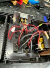
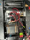
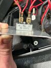
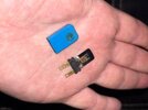
What I’m asking is I think he’s wired the Bridge Rectifier Wrong as he melted the 15 amp Thermal switch attached to the transformer which I have a new one coming for it but whilst I wait I’m reaching out to see if anyone can look at the pictures I have to see if the wiring is wrong or can show me photos of other Turbo 8’s to see the actual way the wiring goes as I don’t want this man to hurt himself or set fire to the History in his collection.
I can relay some information if needed but I don’t have much on the item itself and I have minor understanding of electrics enough to wire up things and Soldering PCB’s etc but with the age of this Charger I want to cast a call for help.
Kind regards
Jay
My name is Jay and I have a Big favour to ask this community so I have an Automotive friend in his 80’s who still rolls around the floor repairing and maintaining his Classic cars like his Morris Minor and Talbot Sunbeam, he bought some joblots on eBay and it had a Selmar Turbo 8 Battery charger but was completely disassembled now he has tried to put it together and I believe it’s not far off.
What I’m asking is I think he’s wired the Bridge Rectifier Wrong as he melted the 15 amp Thermal switch attached to the transformer which I have a new one coming for it but whilst I wait I’m reaching out to see if anyone can look at the pictures I have to see if the wiring is wrong or can show me photos of other Turbo 8’s to see the actual way the wiring goes as I don’t want this man to hurt himself or set fire to the History in his collection.
I can relay some information if needed but I don’t have much on the item itself and I have minor understanding of electrics enough to wire up things and Soldering PCB’s etc but with the age of this Charger I want to cast a call for help.
Kind regards
Jay