Hive Install

Joined
26 Apr 2026
Messages
7
Reaction score
1
Country
United Kingdom
Hi everyone,
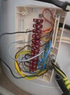
I've made a huge error installing my Hive system, by that i mean I didnt take a picture of the Danfoss WB12 wiring block before disconnecting! I watched a guide that basically said to trace back the black connected to the white wire and swap over the grey. But I mistook part of it and I ended up removing the wrong grey and black and im not 100% sure which one goes where.

I have a danfoss fp receiver which is a straigh swap for the Hive 2 channel controller, I have a boiler in the kitchen (Icos he12) and a separate water tank upstairs (range tribute he). I have fully isolated the old thermostat at both ends which maybe where the problem is (identifying the correct terminals) i have no errors on the hive controller or receiver, however there doesnt appear to be a heat demand going to the boiler as it stays on 0 on the display (should be a c i believe)
 

Attachments

  • 20260426_175057.jpg
    20260426_175057.jpg
    237.4 KB · Views: 15
I've done a bit of reading with the multimeter and watched further videos. I have found the hive receiver hot water and heat demand cables as labelled in the picture, ive connected these to the respective valves.

I'm now left with a grey wire connecting to the white and yellow which seem to be from the tank thermostat.

Hot water

hot water kicks the boiler in when I turn the tank thermo stat up, at this point I'm not sure if its wired correctly (but water is still hot).

heating

the valve opens (tried the lever) but it still isn't kicking the boiler in.

Any help please?
 

Attachments

  • 20260426_193935.jpg
    20260426_193935.jpg
    281.8 KB · Views: 9
If you have removed the room thermostat and not put anything in it’s place, like a link, then you’ve left a circuit open and no way to close it unless you put a link in.
 
If you have removed the room thermostat and not put anything in it’s place, like a link, then you’ve left a circuit open and no way to close it unless you put a link in.
Hi thanks. So comes the question- where does the link go?

Seems in this set up the orange wires from the valves trigger the pump. There's a grey wire from each valve that tie up in terminal 2 with a brown which I was assuming was the boiler.
 
Mid-position zone valve has fire wires, Orange to boiler, White to room thermostat, Blue is neutral, Green/yellow is earth, the Grey wire is domestic hot water off, note off not on, and the motorised valve you can reasonably rely on. Unfortunately plumbers often wire central heating system, and they do naughty things like using green/yellow for other than earth.

With the Y Plan we need both normal open and normal closed from the tank thermostat, and it is common for plumbers to use the green/yellow for one of those.
Hi thanks.
It's entirely possible I'm misinterpreting what you mean. However

Both hot water and heating valves are both wired with 4 core, blue, brown (SL), grey (PL) and orange (appears to be trigger for pump).

I also have a tank thermostat that has earth, white and yellow.

Finally there is a pump, 3 core, brown, blue and earth.

All earth's and neutral are wired at the bottom, and none have been disturbed.

Valve orange wires are grouped with the brown live from the pump.


I then have brown from the hot water valve wired with the yellow from the tank thermo stat.

White from the tank thermo stat is an unknown, it previously had a black wire connected to it, but I don't know if that was from the now removed thermo star or from what I now know to be the hot water demand from the unit downstairs (measures 240v when hot water demand is placed)

Right now I have the previously unknown grey wire connected with the orange wires from the valves. In this configuration the heating triggers the boiler (hasn't dont this all day since I disturbed it)

However I'm not sure if the water demand is working correctly, there is hot water, but im not sure if that has been in there all day unused as no one has been home and used the electric shower earlier
 

Attachments

  • 20260426_231035.jpg
    20260426_231035.jpg
    326.8 KB · Views: 3
Last edited:
Where is the Hive and what is connected to heating on? Essentially, the link needs to be between heating on and the brown of your motorised valve.
 
Where is the Hive and what is connected to heating on? Essentially, the link needs to be between heating on and the brown of your motorised valve.
Hi, so i connected the heating on wire straight into the heating valve brown wire. Is that correct or do I need to link into another wire in addition?

Thanks
 
The problem is, only the motorised valve has fixed colours. We use red, yellow, blue, or brown, black, gray wires because that's what the standard triple and earth colours are, and nothing says what colour should be used for what.

When I moved in here, it was a mess. So I had to work out what cables went from A to B, and how I could best use them to control the heating.

So next is what wireless, and what is wired? My thoughts were batteries become discharged, so anything using a battery needs to be duplicated. So if the battery fails, I can still get some central heating, so main house three thermostats, Nest Gen 3 in the hall, Wiser wall thermostat in living room, and Wiser TRV in wives bedroom, so non are relied on.

So I look at your wiring centre,
1777296511170.png
this is supply to boiler, and the brown in the same cable as the orange wires will be the thermostat corrections will be 3 and 4 in the Hive backplate, and the grey will be line connection and the blue neutral. But as to which brown is DHW and which is CH I don't know.

As to if multi-wireless thermostats can be added with Hive I don't know, they can with Wiser, but not a clue with Hive.
 
The problem is, only the motorised valve has fixed colours. We use red, yellow, blue, or brown, black, gray wires because that's what the standard triple and earth colours are, and nothing says what colour should be used for what.

When I moved in here, it was a mess. So I had to work out what cables went from A to B, and how I could best use them to control the heating.

So next is what wireless, and what is wired? My thoughts were batteries become discharged, so anything using a battery needs to be duplicated. So if the battery fails, I can still get some central heating, so main house three thermostats, Nest Gen 3 in the hall, Wiser wall thermostat in living room, and Wiser TRV in wives bedroom, so non are relied on.

So I look at your wiring centre, View attachment 413531 this is supply to boiler, and the brown in the same cable as the orange wires will be the thermostat corrections will be 3 and 4 in the Hive backplate, and the grey will be line connection and the blue neutral. But as to which brown is DHW and which is CH I don't know.

As to if multi-wireless thermostats can be added with Hive I don't know, they can with Wiser, but not a clue with Hive.
Hi and thanks again.
So last night I believe I've worked out that the left side (of the picture) grey wire appears to be the boiler on. I connected that in place of the black wire above (black is hot water demand).

Once I did that the boiler fires up when a demand is placed in the hive thermostat.

Next I added the black wire (hot water) into white cable of the tank thermo stat and left the above yellow+brown combo as it was. This appears to have also allowed the boiler to fire up when there is a hot water demand. Last night I couldn't effectively test it without tricking the hive system (I increased the required temp on the watwr cylinder thermostat from approx 35c to 45c). That fired up the boiler. In completion I put everything to scheduled, and this morning when I got up the hot water schedule kicked in and fired the boiler up again.

It seems to be working, but I feel like I'm missing this "link" wire
 
Tracing but colours is hard, as I simply don't know where each cable comes from. I made errors with my own, someone clearly though if they select which pumps runs, it will select which area is heated, but it just ran backwards on the circuit without a pump running.

So one has to look at each system independently, what works for me may not work for you, so just guiding you, no attempt at wire A onto hole 1.
 
Hi, so i connected the heating on wire straight into the heating valve brown wire. Is that correct or do I need to link into another wire in addition?

Thanks
It all depends. You mentioned replacing a Danfoss FP - where was this? You may have to check voltages, could be motorised valve failure.
 
It all depends. You mentioned replacing a Danfoss FP - where was this? You may have to check voltages, could be motorised valve failure.
FP was in the kitchen, like for like with dual channel hive. I managed to identify the heat and hot water demand cables doing voltage checks at the main wiring terminal upstairs (as pictured).

The valves appear to be working as the valve tangs lock and unlock as they should. Im also getting both hot water and heating. Just wondering if I'm missing a link they serves a purpose that I'm not aware of
 

If you need to find a tradesperson to get your job done, please try our local search below, or if you are doing it yourself you can find suppliers local to you.

Select the supplier or trade you require, enter your location to begin your search.


Are you a trade or supplier? You can create your listing free at DIYnot Local

 
Back
Top