
You are using an out of date browser. It may not display this or other websites correctly.
You should upgrade or use an alternative browser.
You should upgrade or use an alternative browser.
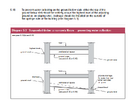
5 in connection 450mm inspection chamber configuration
- Thread starter lu1
- Start date

Is there any scope to run drainage along the Left Hand side of the Building?
The distance between the existing left wall of my bungalow and neighbour's is approx 2.4m Any drains that might go down that alley would be closer to my wall found than 1 metre. With very shallow foundations it's probably not a great area for drain runs and involve lots of concrete fill.
The following may also be relevant - some local BC technical advice is attached.
While the patio to the right and rear of the extension are both 125mm above oversite concrete level i'm (tentatively) assuming a single land drain to the rear (as per the plan) will suffice.
I plan to reduce FGL to the left hand side of the extension by 300mm from patio FGL (i.e. two steps). It will then be 175mm below the extension oversite concrete.
The extension (interior) is 4250mm front-to-back. Sloping each half of the concrete oversite top face downward by about 50mm (approx 1/80) to a central channel and providing drainage by way of a 40mm drain pipe through the left wall seems it might have a chance of approval.
Left side FGL rises to rear patio FGL again at the line of the rear of the existing bungalow but I will keep a 300mm wide channel on my side of the boundaty at 300mm less than rear patio FGL until that interfaces with natural ground level some way to the front of the alley on the sloping site..
Attachments
2.4m is quite wide, I don't see an issue with running a drain through there, provided the existing Foundations aren't undermined.
My basin and shower waste connect directly into soil pipe adjacent the toilet , not an issue for BC.To Building Control e.g. connecting to main sewer for ground floor toilet
My basin and shower waste connect directly into soil pipe adjacent the toilet , not an issue for BC.
Ah, above interior floor level?
I'd like to go straight down through the floor to avoid clutter, if possible.
Edit: ther's a stub stack in the design for the internal bathroom but not the ensuite
Last edited:
2.4m is quite wide, I don't see an issue with running a drain through there, provided the existing Foundations aren't undermined.
Do you imagine an overriding improvement (e.g. dismissing extension/garage alleyway foul complications & garage floor storm I.C. complications) by redesign and trying to send everything down the left, or something more subtle perhaps?
You need to keep things as simple as possible. The further and more complicated route the sewage has to take, the more chance of a problem in the future, in the current design you've got it running round 3 sides of the property.
I'd be looking to bring the Kitchen drainage down the Left side, and it can run parallel with the surface water across the front to pick up the sewer as it leaves the property.
Bathroom Stub Stack in the middle of the build, take that to the right at 90° and join into the run on the right hand side where it meets. Bend can be used to achieve required angle. En Suite, I'd be looking to connect Basin either into the WC drain, or drop the basin and shower into a Bottle Gully immediately outside the property.
Then decide if you really need 110mm Drainage for the Hot Tub, if you don't, then it cuts out all that pipework going to and behind the rear of the build. Air Con drainage could then go into the Rainwater, it's clean water.
That all sounds eminently sensible and deserving of a deep dive - I had expected nothing less from you when I decided to post on the topic. All that and the resident particle physicist's had a bit of a laugh too. What's not to like 
Thanks again.
Thanks again.
A lot of issues with some of those complex runs is the fact that (height position wise), the pipes could clash with each other.That all sounds eminently sensible and deserving of a deep dive - I had expected nothing less from you when I decided to post on the topic. All that and the resident particle physicist's had a bit of a laugh too. What's not to like
Thanks again.
A lot of issues with some of those complex runs is the fact that (height position wise), the pipes could clash with each other.
The fall calculation and positioning of the various elements was actually undertaken exactly so as a clash never occurs (i.e. the whole thing "fits"). There are some close shaves though with foul obvert below to storm invert above down to 50mm (or less) in places. I've no idea if BC would approve such, all dimensions (including crossing gaps) will be in the submitted plan.
Will be working on an update but the garden hot tub drain is definitely toast. There are still some small crossing point gaps possible in the multi-slope driveway

Precision doesn't work like that in the ground. Plus there might be other objects in the ground that could influence the height of the pipes.The fall calculation and positioning of the various elements was actually undertaken exactly so as a clash never occurs (i.e. the whole thing "fits").
Precision doesn't work like that in the ground.
2 metres at 1/40th to close that 50mm gap gives me a fair bit of hope.
I've shifted about 150 tons around (shovel/wheelbarrow) in the back garden so think I already know it pretty well ... groundstation for setting out and Optical Level with tripod/staff, with care, I think i'll be accurate enough.
It is a big job though and with very little previous groundwork there are nerves.
I also need to be very accurate with the new founds / footings due to the required low oversite level so will build them myself too (maybe get labour in to do the above ground blocks).
It's an interesting project until it isn't but will have enjoyed learning to handle a mini digger anyway.
We'll see.
Having discussed the foundation / drainage plans with my neighbour over the holiday period he seemed happy enough with the extension left hand foundation but more concerned about a left hand drain (due to proximity).
There’s no Party Wall Act (i.e. section 6(1) / 6(2) Adjacent Excavation Notice) in this jurisdiction so we'd be required to cope with a claim under common law if that were to ever arise.
I've therefore attached an updated work in progress pdf (had to chop a lot of detail from the underlying svg before it would upload) which, currently, does not include the previously suggested left hand foul run in case this might suffice.
The garden hot tub foul connection no longer exists and all future (potentially 5 of mini split) aircon indoor unit condensates' are shown draining via storm bottle gully traps. The additional IC in the alley (right patio) between the existing garage and extension right hand side also permits the ensuite WC to run along a main channel and all connectors at the foul IC's are now 45° or less.
It's, hopefully, more viable than the original plan and, on first calculation check, all fits and keeps the 450mm IC's (9 of) and single 320mm IC within regulation invert/obverts (I think).
Would appreciate any comment to hint that it could have a reasonable prospect of gaining BC approval – it’s still a bit like a picture of the LHC though, so apologies for that.
Extension oversite concrete drainage query (I hope the plan drawing makes this clearer than the following written description!!)
The reason for the additional shading / colouring along the left side of the extension and existing wall being that i'm not particularly confident of my updated extension oversite drainage scheme described below.
In summary, again, the rear/right patio FGL is above extension oversite concrete by 124mm. That oversite level is the same as the top surface of the existing (150mm thick strip ) rear (entire left-to-right) foundation.
In attempt to provide extension oversite drainage (the regulations require this to prevent pooling), to a lower level exterior finished ground level, i've:
Externally to Extension
1/ At the interface between the rear patio and path (of 1200mm width) to the left of the extension the ground level has been reduced by 170mm (i.e. existing FGL here has been reduced by a 170mm single step down).
Note - if the extension oversite concrete where to be level it would all be (170 - 124) = 46mm above the path
2/ This path continues along the left of extension at the same 170mm reduced level
until
3/ At the interface of this left path and the existing rear foundation there is a 170mm step up (across a width of 750mm portion of the full 1200mm) adjacent to the existing residence left wall. The remaining (outer) path width (450mm) is not stepped up, it remains level at 170mm below rear patio FGL
Note - the 170mm step back up is to the original, non-reduced, FGL at that point. If the step up did not occur then (170 - 124) = 46mm of the existing rear strip foundation would be exposed above ground.
4/ The remaining 450mm portion of the (reduced by 170mm) path continues level toward the front garden along the existing left wall until it intersects with the existing sloping path (whose average fall along the side of the existing wall is 5.7 eightieths)
This 450mm "channel" is bounded on both sides by sections of 90mm width concrete dwarf wall (they have a top elevation with 15mm flat and 75mm sloping). The effective width of the channel is therefore (450 – 2 x 75) = 300mm.
Internally to Extension
A/ At the inner leaf of the rear extension wall and the outer leaf of the rear existing dining room wall the extension oversite concrete is 124mm below rear patio FGL.
B/ The oversite concrete is angled down from both of these boundary locations at 1/80th toward the midline of the extension. The resultant fall is 27mm. This midline oversite is now (46 - 27) = 19mm above the level of the path to the left of the extension.
C/ A 40mm dia pipe exits the 350mm left patio wall at the extension midline. Its internal oversite invert is at 19mm above the extension left path and a 1/80th pipe fall of 4mm sees its invert at 15mm above extension left path (170mm reduced) FGL.
In summary,
(i) The extension oversite concrete drains to the extension (170mm reduced level) left path surface.
(ii) The extension left path level surface drains, via a 300mm wide level (front to back) "channel" (at 2385mm towards the front garden from the existing rear foundation) at the interface between it and the existing (5.7 eightieth fall) sloping left path.
Does that seem reasonable?
PS:
the existing dining room is a Terrazzo/Cement floor which is to be replaced with suspended wooden floor. Its oversite concrete will be at the same level as the extension oversite. The plan drawing shows a similar sloping oversite drainage solution to that described above for the extension but I do not describe that here in case of adding further confusion.
Attachments
Last edited:
DIYnot Local
Staff member
If you need to find a tradesperson to get your job done, please try our local search below, or if you are doing it yourself you can find suppliers local to you.
Select the supplier or trade you require, enter your location to begin your search.
Please select a service and enter a location to continue...
Are you a trade or supplier? You can create your listing free at DIYnot Local
Similar threads
- Replies
- 3
- Views
- 4K
- Replies
- 2
- Views
- 1K
- Replies
- 4
- Views
- 1K