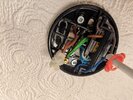
It looks like it's got a feed cable in with a brown and blue, then a cable going out to the switch possibly with 2 browns so the permanent live going to the choc block to connect to the feed live, then the switched live going back to the L terminal (then the lamp).
The blue feed goes to the N terminal then out to the lamp.
So what is the extra blue wire?
If the OP has wired this and needs to check it I would:
During daylight hours, turn off the breaker to the lighting circuit, check for any voltage at the lights with a suitable meter.
After checking the wires are dead/have no voltage on them.
Disconnect all wires (perhaps mark them first), using a multimeter on ohms measure across the brown one that was in the L terminal and the other browns that were in the chock block with someone else flicking the switch to see if that is the switch pair.
Once identified, tape and mark them together so you can move them out of the way.
With all wires disconnected from each other, put the wires into choc blocks/wago's and turn on the power and carefully measure (on AC voltage) between earth and the brown wires to see which one has the permanent live feed.
(this assumes the ground wire is actually connected to ground).
Then between the identified brown live feed and a blue see which one gives a +/-240v reading, hopefully they do not both do so.
That would then identify the feed.
put them in seperate wago's and tape off.
The extra wire, can more be pulled down to enable you to see which individual wires go into a t&e cable, that is likely the loop feed to the next lights. check this pair for any voltage on it too, it's likely to have none.
Here is a handy how to wire it from our very own Flameport.
Adding one or more extra lights so that they are all controlled from a single switch

flameport.com
I'm only the DIY'r, the sparkies (ex or not) will say if I'm advising wrong.