ESI 2 Valve to Tado V3 Wireless

Joined
25 Feb 2026
Messages
2
Reaction score
0
Country
United Kingdom
Hi All,

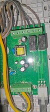
I am currently trying to get Tado V3 Wireless set up on ESI 2 Valve PCB (no hot water). I have followed several threads on here and else where but unable to get it working fully. I have managed to get it into the state in the pictures attached (1st is of the original set up) and can confirm when powered up it calls for heat and hey presto both valves open and the boiler heats the water.

The trouble is the stats didn't call for it and the boiler wont stop, I have tried my best to go through all the threads to see if I had missed anything but cant see my mistake other than buying a house with an ESI set up!
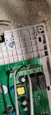
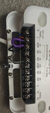
Current wiring
PCB - Receiver
0v - NO
RH - NC
L-L
N-N

Receiver Loop
L-COM

I have tried with the +V wired to NC but that did not change anything.

It has been a very long evening doing this!

Any help would be much appreciated!
 

Attachments

  • IMG20260221100421.jpg
    IMG20260221100421.jpg
    444.4 KB · Views: 19
  • IMG20260225231623.jpg
    IMG20260225231623.jpg
    339.7 KB · Views: 19
  • IMG20260225231659.jpg
    IMG20260225231659.jpg
    221.7 KB · Views: 17
+1 - why are you sending 240V to connections that are marked 5v or even volt free 0V? Not familiar with the ESI PCB 2 valve - is there a link to the MI?

Where does the grey in pick 3 go to, is that split to the greys in pic 2?

Were the browns in pic 1 to the +V terminal originally 240v?
 
Your right, I'm not to sure why I've linked the 230v to the COM on the receiver. I think that was from following another thread and I've forgot to unlink that.

Here is a link to the MI for the two zone valve system. https://support.esicontrols.co.uk/wp-content/uploads/2024/02/CPC2ZP6C-Installer-Instructions.pdf

The grey in pic 3 goes to one of the greys in pic two on the 0v, there is two recovers both wired up like pic 3, one for each stat. So this is linking each RH to NO

The browns in pic one are linked to the ESI Wired Stats on the wall into the +V which is only carrying 5V.

The 230v for the receivers is coming from a junction from the boiler supply to the board at the Valve end
 
I'm not entirely sure, but think you'll need all 3 somehow in the receiver. Perhaps speak to Esi technical?
 
Interesting, looking at the MI, it seems like it may be very specific to those specific stats, given they have 3 matching terminals - +V, 0V, RH

The +V and 0V seems to be the 5VDC switching side but not sure what RH would be, maybe something to do with hysteresis for the stats and in effect could be a N but it's not clear and there's nothing in the MI indicating what RH may be. Also, given you have shunted 240V down that RH line I'm not sure what the outcome of that may have been for the controller.

I'm not even sure that the TADO would be compatible with that controller. As suggested, ESI Tech may be able to tell you if you can use TADO and if so how it would be wired.
Read the post several times
My take is you are going to use Tado to control heating and hot water cylinder each zone having its own MV.. The controllers would have been dedicated ESI ones

Tado will be able to control the motorised valves directly
Motorised valves have aux switch, which controls the boiler.
Regardless of which MV is open, the boiler will run until the MV closes. Ensure boiler does NOT need a bypass post valve closure. To function with Tado, you will need to replace the heads on the motorised valves

ESI stats need to be utilised to give you OT function. OT stats operate at 5 volts supply. Doubt ESI power supply unit will be compatible with Tado. Could make it function but how well is the question

Tado is a programmer so are the two ESI stats and right away you have a conflict
Does your boiler support OT switching?

If 240 volts has been applied to terminals that output 5 volts to what would have been 5 volt supply for OT stats, Those capacitors on the PCB will not be happy
 
Last edited:

If you need to find a tradesperson to get your job done, please try our local search below, or if you are doing it yourself you can find suppliers local to you.

Select the supplier or trade you require, enter your location to begin your search.


Are you a trade or supplier? You can create your listing free at DIYnot Local

 
Back
Top