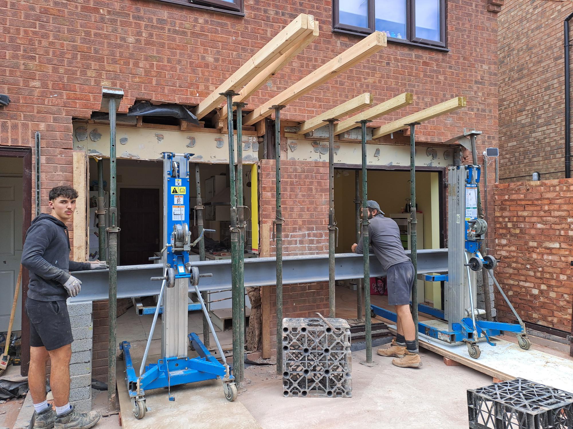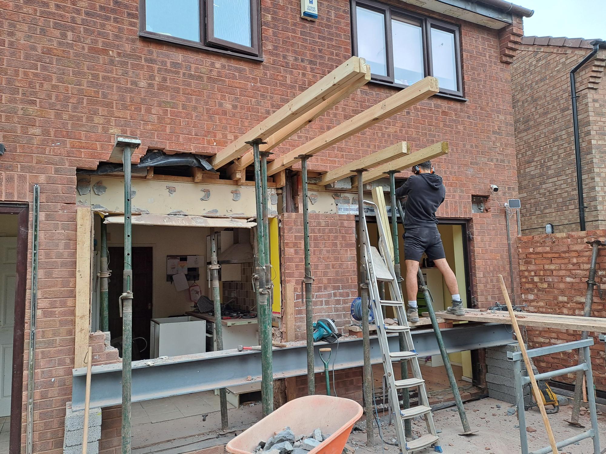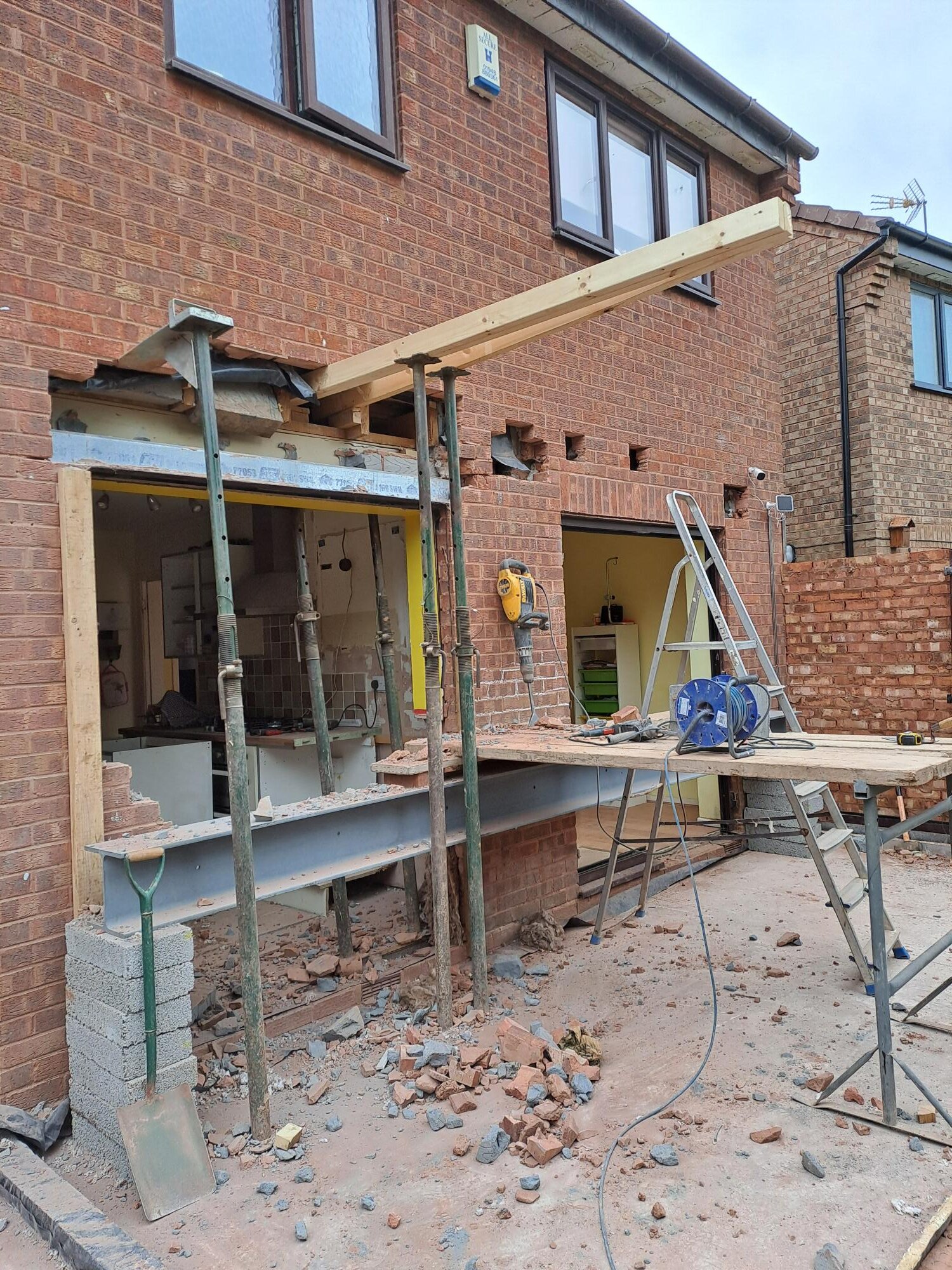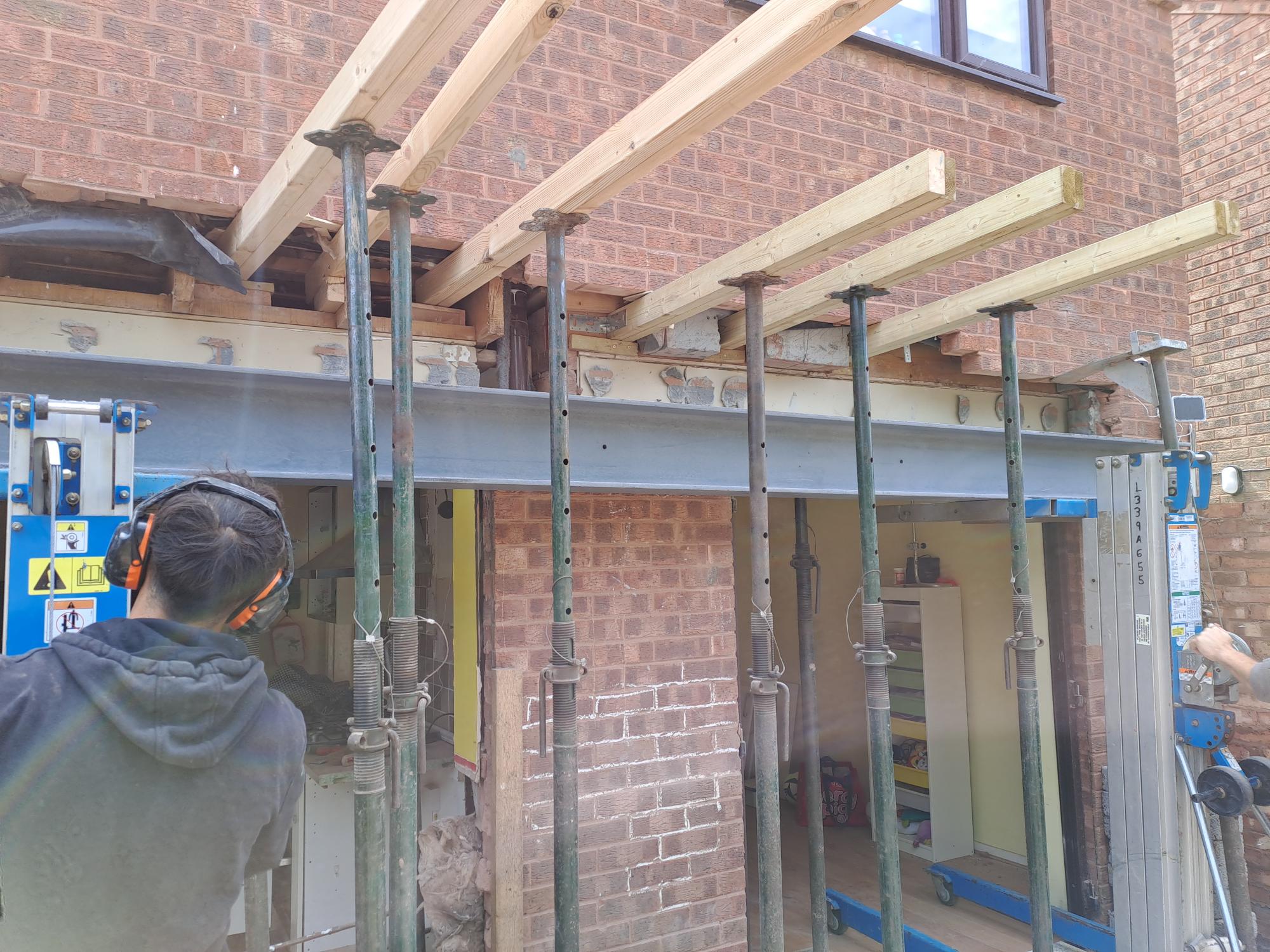
6.5m Goal post RSJ

Joined
21 Jul 2026
Messages
3
Reaction score
0
Country
United Kingdom
Hi All,

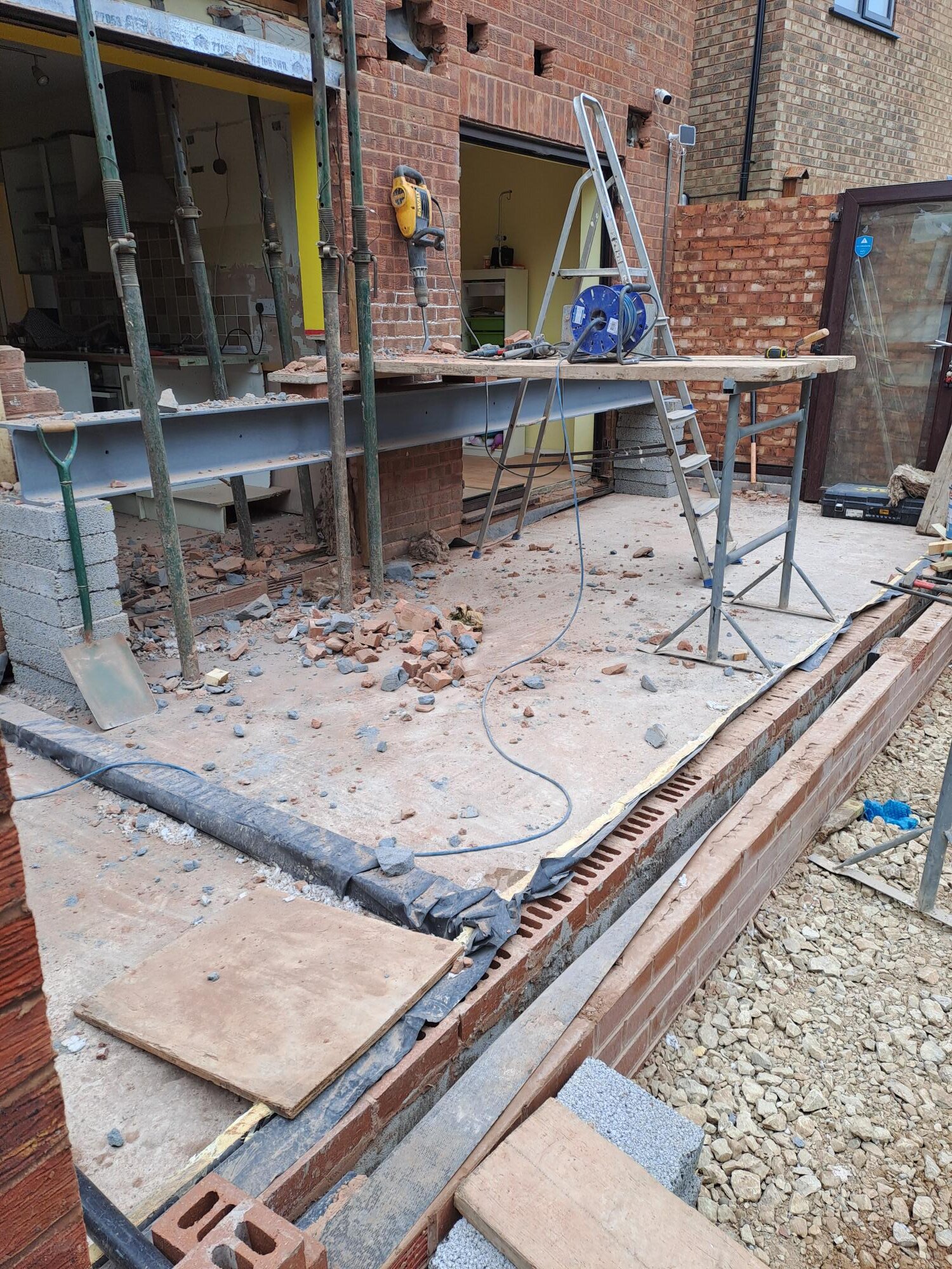
I'm planning on opening up the rear of my house and could do with a little advice; I'm exhausting the internet and youtube.

The Structural Engineer has specified a 305x305x118 6.5m long beam bolted to the sides of two 203x203x46 columns (B6, C1 LHS and C1 RHS).
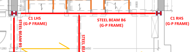
1784661901489.png


The columns are to be sat on two 1.5x1.5m 0.5m deep pad foundations, which overlap the current foundation. They have specified that the current foundations are to be replaced by the pad and dowels used to tie the pad to the rest of the foundation.

I believe the only way to guarantee the columns and beam mate perfectly is to assemble before bolting down the columns. My plan would be to lift the beam into position then raise the columns and bolt together. Once the position is set, which I imagine will be tricky due to the weight, the holes can be drilled into the pad and the chemfix anchors installed.

Does this seem reasonable?

The SE has specified 15mm of non-shrink grout under the base plate.
Does this mean I should rest the columns on a 15 mm steel spacer, plus extra to get it plumb? In which case couldn't I just get a 15 mm square spacer welded to the centre of the base plate?
I was thinking of using adjusting nuts between the pad and base plate, but once the holes are drilled I don't fancy moving the entire goal post to fit the nuts.
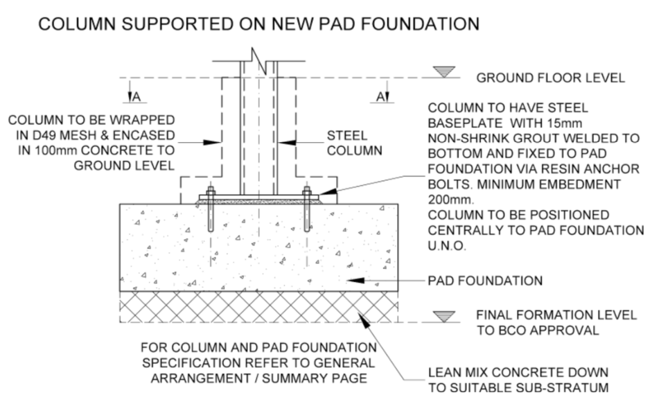
1784661624822.png
 
Hi All,

I'm planning on opening up the rear of my house and could do with a little advice; I'm exhausting the internet and youtube.

The Structural Engineer has specified a 305x305x118 6.5m long beam bolted to the sides of two 203x203x46 columns (B6, C1 LHS and C1 RHS).
View attachment 418886

The columns are to be sat on two 1.5x1.5m 0.5m deep pad foundations, which overlap the current foundation. They have specified that the current foundations are to be replaced by the pad and dowels used to tie the pad to the rest of the foundation.

I believe the only way to guarantee the columns and beam mate perfectly is to assemble before bolting down the columns. My plan would be to lift the beam into position then raise the columns and bolt together. Once the position is set, which I imagine will be tricky due to the weight, the holes can be drilled into the pad and the chemfix anchors installed.

Does this seem reasonable?

The SE has specified 15mm of non-shrink grout under the base plate.
Does this mean I should rest the columns on a 15 mm steel spacer, plus extra to get it plumb? In which case couldn't I just get a 15 mm square spacer welded to the centre of the base plate?
I was thinking of using adjusting nuts between the pad and base plate, but once the holes are drilled I don't fancy moving the entire goal post to fit the nuts.

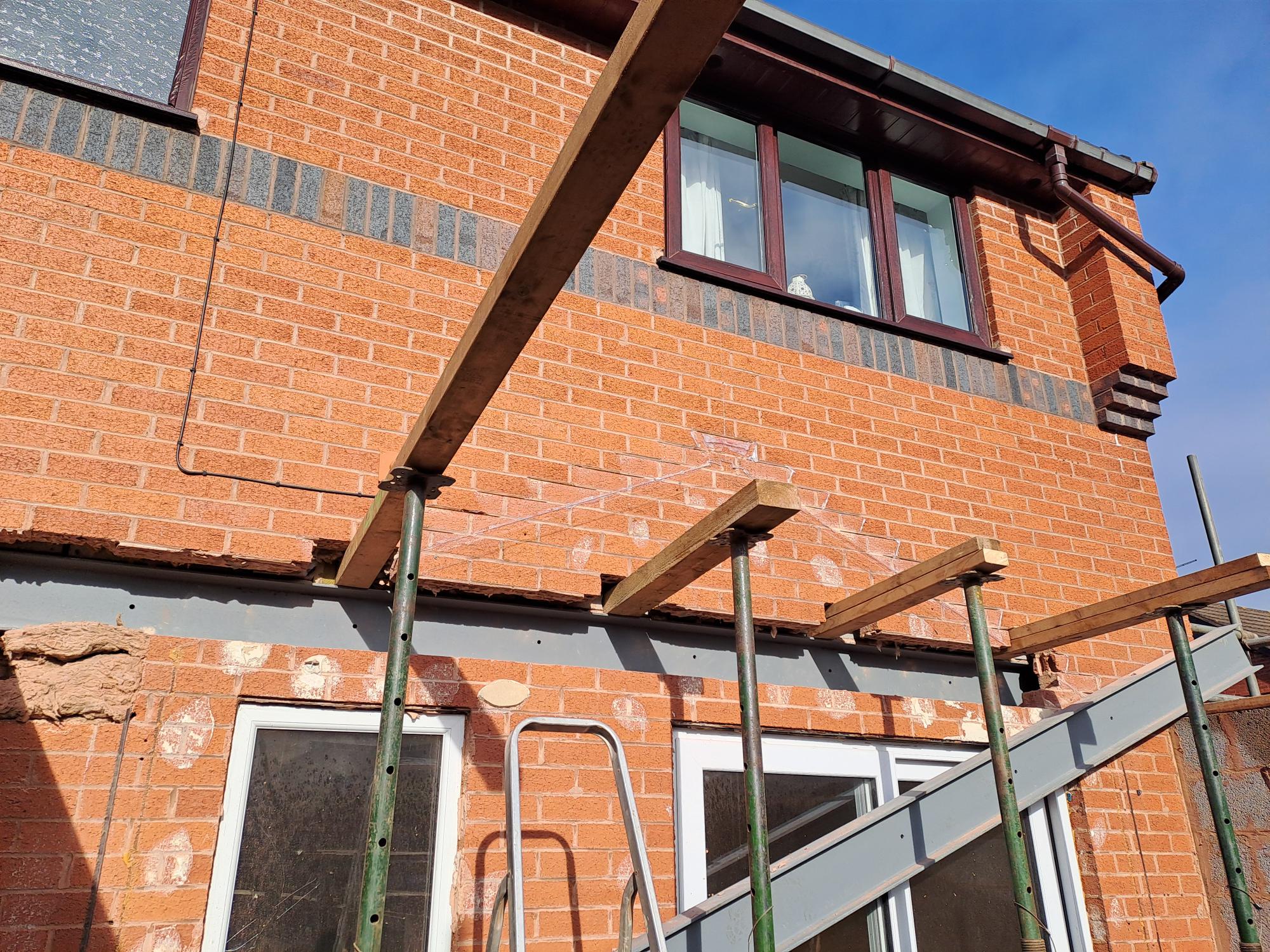
View attachment 418885
Sounds like a plan yes.

We'd likely make the pad shape large enough so that it could accommodate the acro props whilst not interfering with the column positioning.

Dn't forget that if you are using Genie lifts they need an even base to travel on. You may need the beam in position before you start your needles and props.


That is a massive beam. Given you have no buttress on the right hand side the whole thing is acting as a sway brace which means that the columns are considerably bigger than they would be to provide simple support to a beam, but the beam can then generally be smaller than if it was just a simply supported one as the columns take some bending force. I wonder if your SE has been overly cautious? (Absolutely not a bad thing if one is going to err!)

I agree with Noseall's comments but would add the point that the 15mm grout is not critical dimension: it's there to give you some tolerance, so don't get hung up on that.

Finally, the tone of your question suggests diy? This is a mahoosive job: I'd thing long and hard about trying it.
 
A 305 x 305 .......wow, just......wow!
They could have done with the OP's engineer to oversee the Pfeizer building in Manhattan!
 
Last edited:
I did challenge the SE about the size of the beam as it is enormous! Their response was:
"The reason for such a big beam here is the fact that we have a goal-post frame here to provide proper global stability of the building. The beam section is so big to have a stiff connection between the beam and column to limit the column deflections. Another idea would be to provide bigger columns, but this means the columns would then be much heavier then beam."

Yeah, we are considering DIY'ing it. Potentially using a mini-telehandler for lifting the beam. What ever could go wrong...
We are also getting quotes from builders to do the install too, so we're not completely mad.

Regarding the grout, I understand it's there to get a close-to-perfect contact between the pad and the column base.
Is the grout fluid enough to flow between the two surfaces if the base is fastened to the pad and there are only the minor undulations of the concrete for the grout to flow in?
 
I did challenge the SE about the size of the beam as it is enormous! Their response was:
"The reason for such a big beam here is the fact that we have a goal-post frame here to provide proper global stability of the building. The beam section is so big to have a stiff connection between the beam and column to limit the column deflections. Another idea would be to provide bigger columns, but this means the columns would then be much heavier then beam."

Yeah, we are considering DIY'ing it. Potentially using a mini-telehandler for lifting the beam. What ever could go wrong...
We are also getting quotes from builders to do the install too, so we're not completely mad.

Regarding the grout, I understand it's there to get a close-to-perfect contact between the pad and the column base.
Is the grout fluid enough to flow between the two surfaces if the base is fastened to the pad and there are only the minor undulations of the concrete for the grout to flow in?
Use a hammer drill to vibrate the steel and help with the grout flow.
 
"The reason for such a big beam here is the fact that we have a goal-post frame here to provide proper global stability of the building. The beam section is so big to have a stiff connection between the beam and column to limit the column deflections. Another idea would be to provide bigger columns, but this means the columns would then be much heavier then beam."

All that is necessary is a properly detailed connection which could include a knee brace. The beam itself doesn't need to be deep to get a stiff joint.

My gut feeling is that this is overdesigned.

One of my clients had a similar opening (6.6m) and the solution for this was 203x203x86kg/m UC for the beam and 203x203x52kg/m UC for the posts. The joints were carefully detailed to provide bending strength round the corner.

This was designed by an SE as it was beyond the scope of my PI and was approved by the most nitpicky checking engineer in the history of BC!
 
Last edited:
I feel like it is unnecessarily large too.

Do you have an example of the joint used to achieve the stiffness please? I want to go back to the SE with a suggestion as they didn’t seem overly excited about changing the design when I first challenged it.
 
I feel like it is unnecessarily large too.

Do you have an example of the joint used to achieve the stiffness please? I want to go back to the SE with a suggestion as they didn’t seem overly excited about changing the design when I first challenged it.
Here's the detail.

The house is a big 4 bed semi and this was the whle of the downstairs back wall being removed, so doubtful if yours is greatly different loadwise.

SEs don't tend to like being questioned I'm afraid!
 

Attachments

Here's the detail.

The house is a big 4 bed semi and this was the whle of the downstairs back wall being removed, so doubtful if yours is greatly different loadwise.

SEs don't tend to like being questioned I'm afraid!
I agree that a suitably-stiff joint is the key to 'spreading out' the bending moment between the beam and columns so that they all work together. But before I saw the detail I wondered how they would get sufficient bolts in what is a relatively shallow (203) beam, but then noticed that they've got an extended end plate for the extra two bolts. The web stiffeners look correctly-spaced - all in all a decent joint design for a moment frame, IMO.
Compared with this, the 305 deep beam looks a bit of a rookie design, unfortunately (not that it would fail, but a bit over the top).
 
I feel like it is unnecessarily large too.

Do you have an example of the joint used to achieve the stiffness please? I want to go back to the SE with a suggestion as they didn’t seem overly excited about changing the design when I first challenged it.
The reason why they are reluctant to change the detail is that doing so would make them look idiots as though they didn't know what they were doing.
You might have an uphill struggle with that!
 
You stand to gain 100mm under the beam: that's not insignificant. The steel savings would probably at least partially be taken up by increased fabricating costs, though we don't know what sort of a detail your guy was using.

I'm sure some SEs have shares in steel suppliers!!
 

If you need to find a tradesperson to get your job done, please try our local search below, or if you are doing it yourself you can find suppliers local to you.

Select the supplier or trade you require, enter your location to begin your search.


Are you a trade or supplier? You can create your listing free at DIYnot Local

 
Back
Top