Adding air to Stuart Turner pump

Joined
15 Nov 2015
Messages
44
Reaction score
0
Country
United Kingdom
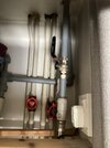
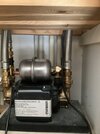
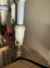
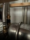
For some time our shower pump, which also pumps the bathroom sink taps, has had to be topped up with air every 6 months. Intermittent hesitation of water at the sink and shower, leading to longer periods waiting for the water to come through. ST have said they cannot supply replacement seals as the pump is too old. Fed up with paying for a plumber to come and do it and was wondering if I can instead, to keep it going a bit longer (putting off paying £500 to replace). Can someone tell me what I need to switch off and where please and also how much air to add. I know nothing about plumbing but then the last plumber didn’t seem to either Any advice welcome. Thanks so much!
 
Sponsored Links
I assume you are talking about a negative head pump, the type with a pressure vessel on the top, if so, they are fitted with a Schrader Valve the same as fitted to car tyres, so can be repressurised using a footpump with a pressure gauge on.

Repressurising is done with the power to the pump off and the water inlet valves closed. The outlet valves / taps should be open so that any water displaced by the re-pressurising can be expelled. The pressure required varies according to the pump which will be given in the installation instructions, along with any other pump specific information.
 
Thank you so much for your reply. Please could you tell me which valves I need to close from the photo. No knowledge of plumbing whatsoever
 

Attachments

  • IMG_0639.jpeg
    IMG_0639.jpeg
    256.1 KB · Views: 29
  • IMG_0640.jpeg
    IMG_0640.jpeg
    214.7 KB · Views: 28
One end of the pump is for pumping hot water and one end is for cold water. I can't see where the pipes go in your photos, but if you look at the diagram below which is from an ST manual, I've highlighted the inlet pipes.

aaa.jpg


You will see that they are the pipes coming from the hot and cold water storage. They should be closed when re-pressurising. In the diagram there are valves installed as part of the inlet hoses, or you may have stop taps (marked with a 1 on the drawing) in other locations on the pipes supplying the pump with hot and cold water.

The other two pipes from the pump will be the outlet pipes that go to the shower & bathroom taps, which should be open when re-pressurising.

Another clue is that on the pump itself, there might be arrows showing the direction of water flow. The inlets will have arrows pointing towards the pump and the outlets will have arrows that point away from the pump.
 
Last edited:
Sponsored Links
Thanks very much for taking the trouble to do this. Not feeling overly confident as the diagram doesn’t match with our pipework in the airing cupboard. It’s like Spaghetti Junction in there!
Are the silver screws the things I should turn to shut off as shown in the first photo?
In the second photo which shows 2 pipes going to the pump (2 exactly the same on other side, not pictured) is it the pipes with the black plastic bit I’m isolating?
What can go wrong if I cock it up?!
Thanks again
 

Attachments

  • IMG_0084.jpeg
    IMG_0084.jpeg
    184.4 KB · Views: 22
  • IMG_0085.jpeg
    IMG_0085.jpeg
    203.7 KB · Views: 15
That looks like an isolation valve, I can't see your installation well enough from photos to know what goes where, and if you're not able to work it out by looking at your installation, then I would suggest perhaps that you engage the services of the plumber who has done it before once more and watch him carefully. Then you will know what to do in the future.
 

DIYnot Local

Staff member

If you need to find a tradesperson to get your job done, please try our local search below, or if you are doing it yourself you can find suppliers local to you.

Select the supplier or trade you require, enter your location to begin your search.


Are you a trade or supplier? You can create your listing free at DIYnot Local

 
Back
Top