Can I automatically switch a fridge between 2 sockets?

Sponsored Links
I would avoid the use of electronically delayed relays. More to go wrong.
That's true. Simple is always nice.
Simple slugged relays are far more reliable. http://www.dfrtelecoms.org.uk/pdf/relay.pdf
Look at page 2 where the operation of slugs delaying the operation of relays is described.
Those are what I brought up on, and I probably still have a few slugged PO relays in the cellar (although I certainly wouldn't use them to switch 230V). However, I'm not sure that it is possible to get just 'slow operate' functionality with a slug, is it? - 'slow release' or 'slow operate AND release' are easy (according to which end one puts the slug), but I'm not sure that just slow operate is possible. I'll have to think about that - and whether 'slow operate and release' would be OK for my application - as well, of course, as ascertaining whether slugged relays (not ancient PO ones!) are currently 'readily available'.

Kind Regards, John
 
The use of a second winding with a own relay contact is probably the better way.

I would use then to switch a 12 volt control circuit on safety ground. That said I have used them to switch 230 volts but I was younger and not so well informed then....... ( I had tolerant parents )
 
The use of a second winding with a own relay contact is probably the better way.
That might prove difficult to find - certainly on an 'ongoing availability' basis.
I would use then to switch a 12 volt control circuit on safety ground. That said I have used them to switch 230 volts but I was younger and not so well informed then....... ( I had tolerant parents )
Same here (although, in my case, my parents probably didn't even know!). Using a 12V control circuit would, of course, necessitate having two 12V PSUs, one powered by each phase, which would further complicate matters (and would move us a bit further from KISS, since there would, again, be more things to go wrong - albeit probably in a 'failsafe' sense).

I'll give a bit more thought to all this. Do you know if any 'electromagnetically delayed' relays (c.f. the slugged PO ones) are made these days?

Kind Regards, John
 
Sponsored Links
.... Using a 12V control circuit would, of course, necessitate having two 12V PSUs, one powered by each phase, which would further complicate matters (and would move us a bit further from KISS, since there would, again, be more things to go wrong - albeit probably in a 'failsafe' sense).
My brain is working slowly today. If I wanted to use slugged relays (even if they are still made), I would be stuck with having to use (probably two) DC PSUs, anyway.

Kind Regards, John
 
12 volt battery, charged by with of the supplies. Charging can be manual operation.
Something else to go wrong (this time 'flat'), although again probably fail-safe. However, I think the number of relays/contactors may be escalating - we need at least one with a 230V AC coil (unless we introduce more things to go wrong) to sense the presence of power, one with a DC coil to be slugged (if we can find such a relay), and at least one or two relays/contactors to effect the actual changeover.

I'm going to try to clear my mind and start thinking about this exercsie again from 'square one'.

Kind Regards, John
 
Using a current limiting capacitor and resistor a PO 3000 type relay can be used to sense mains available. Provided the core is earthed it appears to be safe as regards isolation between coil and contacts. This is NOT an approved use of PO 3000 type relays

But in this case there might be two "earths" one from each of the supplies.

To use a common earth do we need to isolate one one or both supply via an isolation transformer


Starting again from cube one.

Have a fridge with two independent refridgeration circuits each with its own compressor.
 
Using a current limiting capacitor and resistor a PO 3000 type relay can be used to sense mains available. Provided the core is earthed it appears to be safe as regards isolation between coil and contacts. This is NOT an approved use of PO 3000 type relays
Yuk :)
But in this case there might be two "earths" one from each of the supplies. To use a common earth do we need to isolate one one or both supply via an isolation transformer
Possibly in the OP.s case, but not mine. In my case I simply have just two phases of the same 3-phase installation, which has only one earth.
Starting again from cube one. Have a fridge with two independent refridgeration circuits each with its own compressor.
Again, that would only be applicable in the OP's case (my load is not a fridge). An animal such as you postulate could well be impossible to buy off the shelf, hence potentially very expensive. I also wonder if one might have problems of 'hunting' between the two refigeration circuits - presumably one would have to have two thermostats set at appreciably different temperatures.

The analogous solution (duplication of loads) would also be theoretically applicable in my application, but that would be intellectually pretty unsatisfying - being almost an 'admission of defeat' as regards electrical/electronic solutions!

The daft thing is that all that theoretically is really needed is a meaty DPDT relay/contactor (and nothing else) - maybe a solenoid-operated version of a big heavy manual c/o switch - but such animals either don't exist or are very difficut to find. Maybe a fat solenoid (or motor) coupled to a manual c/o switch would actually be the solution!!

Kind Regards, John
 
I'll look out the circuit diagram. I remember that it was far from easy, and that I was not even totally comfortable with the end result. IIRC, the main problem occurs 'at energisation'.....
OK, here’s the present arrangement I have for 
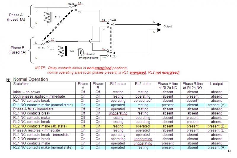
MY application (not the OP’s) for switching a small load to an alternative phase (of a single 3-phase supply) in the event of failure of the usual phase:
For the primary ‘interlocking’, I rely on the intrinsic ‘interlock’ functionality of changeover relay contacts. The risk of doing this is obviously that of arcing between (or fault-produced contact between) the two fixed contacts, if they are (as they would be in the simplest arrangement) connected to different phases. However, assuming I’ve got it all right (see table above), the logic of my control arrangement is such that, in all normal operating conditions (including loss and return of the primary phase), both phases are never connected to a set of relay RL2’s changeover contacts simultaneously. This also remains true if relay RL1 fails to operate (or its contacts stick in NC position) or if its contacts remain stuck in the NO position. Failure of RL2 to operate, or sticking of its contacts in either position, has no ‘safety’ implications (although will obviously affect functionality).

In the absence of any faults, the only situation in which both phases could appear on their respective contacts of relay RL2 is very transiently during power-up (of both phases simultaneously), should RL2 change state before RL1 removed the supply to its coil. However, that probably wouldn’t happen and, even if it did, would require an extremely improbably concurrent other fault/issue to result in any problem.

There do, of course, remain some theoretically possible, but very improbable, failure modes - most, if not all, involving faults in the changeover relay itself. However, both phases are supplied from their own dedicated 6A RCBOs and also supplied via 1A (not 3A as I previously said) fuses, and I would imagine/hope that at least one of these devices would operate before anything nastier happened in the event of any of the possible fault conditions. There is also (not shown in above diagram) a relay across the output of RL2 which causes a (battery-powered) alarm to sound should the load receive no power from either phase.

I really am pretty comfortable with this arrangement, but I’m sure that some of you will have some comments, and quite possibly reservations, about it! Posting ‘what one has done’ is always dangerous :) I imagine that it's asking far too much to even hope that no-one will find any fault with it :)

Kind Regards, John
 
I've only skim read the topic but whats wrong with a 3 pole DPDT relay?

00D11CE9-4141-4DE9-A977-85FBC4603FE3-30781-00003022E60DE950.jpg
 
I've only skim read the topic but whats wrong with a 3 pole DPDT relay?
Well, firstly, in my application, it's two phases of a single supply, hence only one earth, hence no need to switch the E (hence my C/O relay only needs to be DP). If it were two totally different supplies, maybe with different earths, (as may be the case for the OP), then one would do do something about the earthing - but would have to think very carefully about the safety and compliance of switching the earth per your proposal.

As per earlier discussions, and as I said in my recent post, the problem/risk of just using a standard relay in the very simple way you suggest, is that one has the two supplies (in my case two phases - so definitely an appreciable PD between them) permanently connected to the pairs of fixed contacts of the relay. An arc from 'one side' could therefore theoretically extend to t'other fixed contact, thereby 'joining' the supplies (or phases) - and some internal relay faults could have a similar effect. My arrangement ensures (I hope!) that (virtually) never do both supplies/phases appear simultaneously at the relay contacts.

Kind Regards, John
 

DIYnot Local

Staff member

If you need to find a tradesperson to get your job done, please try our local search below, or if you are doing it yourself you can find suppliers local to you.

Select the supplier or trade you require, enter your location to begin your search.


Are you a trade or supplier? You can create your listing free at DIYnot Local

 
Sponsored Links
Back
Top