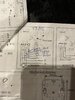
The old stat isn't one I've seen before and the diagram is slightly unusual, however there are some clues.
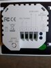
Terminals 1 and 2 in the new stat are a voltage free switch
As are 2 and 1 in the old stat
So based on the above it appears that:
- Old stat 2 would correspond to new stat 1
- Old stat 1 would correspond to new stat 2
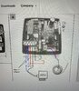
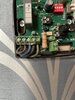
As per the below diagram, terminal 4 is shown connected to N. So I'm a bit surprised to find that in your photo terminal 4 looks to have a brown (live?) wire in it
So the remaining connection would seem to me to be the live, maybe they are using P to mean 'Phase' which I've not seen before. But I think it would seem appropriate for a live supply from a programmer / timeswitch to be the L connection. [If the new stat incorporates both time and temperature control, any existing programmer / timeswitch would need to be set so that the heating is permanently on]
However, this is just my interpretation based on the information you have given, so shouldn't be taken as gospel. Ideally the wires should be traced to their origin to find out what is connected to the other end of them, and tested with a multimeter to make sure.
The hand written wire colours on the diagram you posted doesn't match your photo, so I assume that's another installation?