Communal stairway lighting - wiring diagramme

Joined
19 Jan 2005
Messages
1,171
Reaction score
41
Country
United Kingdom
Hi everyone

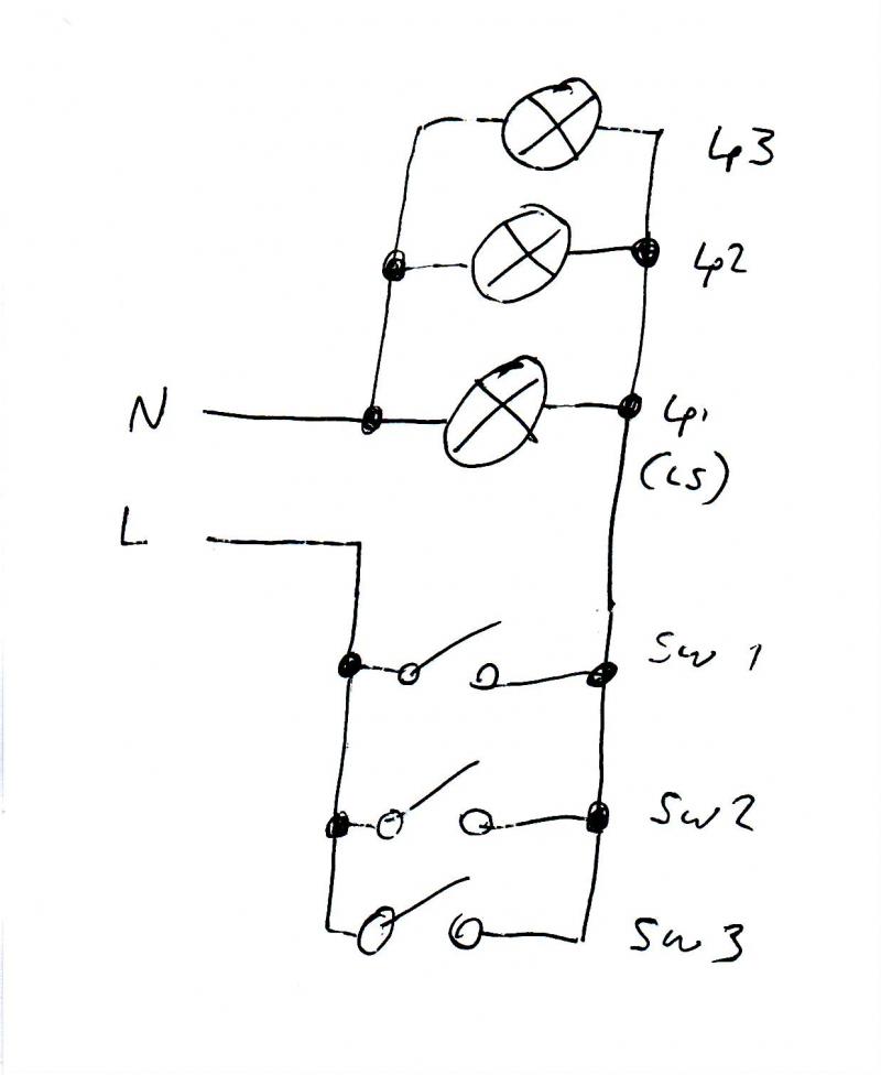
It's Friday and I need to find a diagramme of communual stairway lighting arrangement - two wire at switch (ie no neutral).

I've tried seraching, but can't find anything. Can anyone else help?

Thanks

SB
 
Sponsored Links
So standard loop in system with live and switch return at the switches?

If so then you'll find that in the Wiki.
 
Thanks Gary for reply

Is it that simple? The scenario is multiple lights on one switching arrangement - but switched from any switch.

I understand how this could be done with two way switching and intermediates with one 'load', but that would require 3 core/strapper between each switch. How does it work with only perm live and switched live at each switch? Is the strapper elsewhere?

Am I making things too complicated??
 
Multiple switches would require two 2-way switches and any number of intermediates (obviously).
Either connect them up using a live and switch return to the first switch then 3 core and earth to the first intermediate, second, third........then finally to the second 2-way switch. Preferred option and your suggestion.
The other option would be to take the live supply to the common terminal at the first 2-way switch and the switch return to the common terminal at the second 2-way switch with t&e looping between to include the intermediate switches. This is generally only considered when using single pvc conductors in conduit or trunking though.

Is there any reason why you prefer not to use 3 core and earth between switches?
 
Sponsored Links
Time delay switches can be used in communal stairways and they don't require a neutral at the switch. They can be used to operate the same light. Just wire all the perm lives and return lives in parrallel at the light fitting.
 
Two options which spring to mind:
the pneumatic type switch, each set to the desired time at each point
or
momentary push button switch at each point feeding into a timer which can be mounted in a DIN type enclosure, such as: clicky
 
Now I am getting confused! I should have said in my original post that this is not something I am installing, but an existing install which I want to get a picture of - ie how has it been wired.

It is indeed the push button timer switch scenario. Only 2 conductors at each switch (no N). Have not been able to look in the light fittings as I only had my shortie steps.

I sort of assumed that there was a fairly standard way of doing this type of lighting as it's quite common - but maybe not!

Where does the switching all happen? Presumably at one of the light fittings and the rest are connected as a load? What I'm failing to see (bear with me please!) is how the switch lines at any switch can connect the load.

Am I still being dense?
 
its just like a normal light, but with two or more lights.

each extra light is daisy chained from the first. (in paralell)

like wise so are the neumatic switches, they are all daisy chained together, (in paralell) push any one all said lights come on for as long as that switch takes to turn off. push another swithc after the first and they will saty on untill the 2nd switch turns off
 
Thanks everyone it's finally sunk in. Special thanks to spark 123 - a picture speaks a thousand words, eh?

SB
 

DIYnot Local

Staff member

If you need to find a tradesperson to get your job done, please try our local search below, or if you are doing it yourself you can find suppliers local to you.

Select the supplier or trade you require, enter your location to begin your search.


Are you a trade or supplier? You can create your listing free at DIYnot Local

 
Sponsored Links
Back
Top