Cooker supply

Joined
4 Jan 2014
Messages
224
Reaction score
4
Location
Norfolk
Country
United Kingdom
Hi all, just planning the wiring for my kitchen extension.
The induction hob will be 7.2kw and will have two single 3.3kw ovens so a total of 13.8kw.

I beleive anything under 15kw can be on a 6mm wire or will it need to be 10mm? The trip is also a B32. The appliances will be about 9 meters away from the consumer unit.

Also I presume this can be run into one cooker switch with a double outlet to run to two wall outlets - one for hob and one for both of the ovens.

I hope this makes and thanks in advance.
 
Sponsored Links
No, it could be 4mm²

Note the use of the word "could"

What EFLI is implying is that whilst 4mm² cable might be adequate, depending on a number of factors it might need to be 6mm² or even 10mm²

The suggestion is that you don't (currently) have the knowledge needed to design the circuit. That gives you two choices (1) acquire that knowledge or (2) get someone who already has it to do it for you.
 
Sponsored Links
Note the use of the word "could"

What EFLI is implying is that whilst 4mm² cable might be adequate, depending on a number of factors it might need to be 6mm² or even 10mm²

The suggestion is that you don't (currently) have the knowledge needed to design the circuit. That gives you two choices (1) acquire that knowledge or (2) get someone who already has it to do it for you.

I was going to put 6mm in based on other research. I was going on this forum hoping someone might offer some advice to back it up. Davelx... you sound like you could help or point me in the direction of how I can help myself. How would an electrician work this out. I would presume that most of the time they would just know and for the rest they have an easy to read chart or if they really needed to they would do the calcs??
 
Actual length of cable and installation method all dictate the current carrying capacity. Look at volt drop and derating factors for things like insulation or conduit (tlc direct have useful tables on their website)
 
I was going to put 6mm in based on other research. I was going on this forum hoping someone might offer some advice to back it up. Davelx... you sound like you could help or point me in the direction of how I can help myself. How would an electrician work this out. I would presume that most of the time they would just know and for the rest they have an easy to read chart or if they really needed to they would do the calcs??

OK, let's treat this as a design exercise. To start with, you need some basic information:

1) What earthing system is used in your installation (TN-C-S, TN-S or TT)? If you don't know, post a good quality photo showing your service head (cut out/main fuse), meter and consumer unit and all the connections between them.

2) What is the maximum length of the cable run between the consumer unit and the cooker connection plate?

3) Provide a detailed description of the environment through which the cable run will pass; what is under it? around it? over it? how is it to be supported? will it run close to any other cables and if so what are those cables supplying?

These enable us to select the size of cable to ensure that (a) the overload & fault protection device (MCB) will function correctly (b) the cable will not overheat and (c) the voltage drop in the cable will not be too great (d) the cable can be
adequately supported so that in the event of a fire it will not fall and cause a shock hazard.
 
Last edited:
So to question 1 please see below pictures.
Question 2: Maximum length will be 14 meters

Question 3: C/U is in garage so the wire will first be going along the top of two walls in some conduit for about 7 meters, it will then go into ceiling void where there is some rockwool type insulation so will be attached to joist. It will then drop down into a chased concrete block wall and terminate at the cooker switch and go no more than 2 meters to hob and no more thab 2 meters to ovens.

I hope that is sufficient?
 
Last edited:
jeezzz

tails in a junction in pic 1 :eek:

ring transformer out of enclosure in pic 2 :unsure:

Hey, what do you mean by tails in pic one please? Do you mean the terminal block? What can I do to make better?

Presumably the ring transformer needs to be in an enclosure? (installed before I moved in).

Thanks
 
Hey, what do you mean by tails in pic one please? Do you mean the terminal block? What can I do to make better?
Yes the terminal block. The best thing you can do is call your electricity supplier and ask them to come and fit an isolator between meter and CU. DON'T tell them about that lashup til the engineer arrives, play dumb (just moved in or it was in some trunking or some nonsense like that). If you're lucky they won't bill you.
Presumably the ring transformer needs to be in an enclosure? (installed before I moved in).

Thanks
And fixing to something

You might want to move your collection of G clamps as well, lead pipe is not very strong.
 
Yes the terminal block. The best thing you can do is call your electricity supplier and ask them to come and fit an isolator between meter and CU. DON'T tell them about that lashup til the engineer arrives, play dumb (just moved in or it was in some trunking or some nonsense like that). If you're lucky they won't bill you.

And fixing to something

You might want to move your collection of G clamps as well, lead pipe is not very strong.

What would be my reason for an isolator... I.e if I'm going to play dumb what is my reason for asking for it etc?

I didn't realise ut was lead pipe... I assumed it was steel..?
 
You're looking to upgrade the CU, an electrician who came to quote advised you to get an isolator fitted first, saves having to have the supplier or DNO on site to disconnect while the CU is swapped.IF engineer questions you further, again play a bit dumb, tell him electrician mentioned needing a metal cu cos 18th edition. Engineer with luck will say "bloke's a con artist, nothing wrong with that board unless you're adding 6 circuits. Now, where do you want this isolator?"

The black bits of that pipe are iron or steel, the grey bit is lead.
 
Last edited:
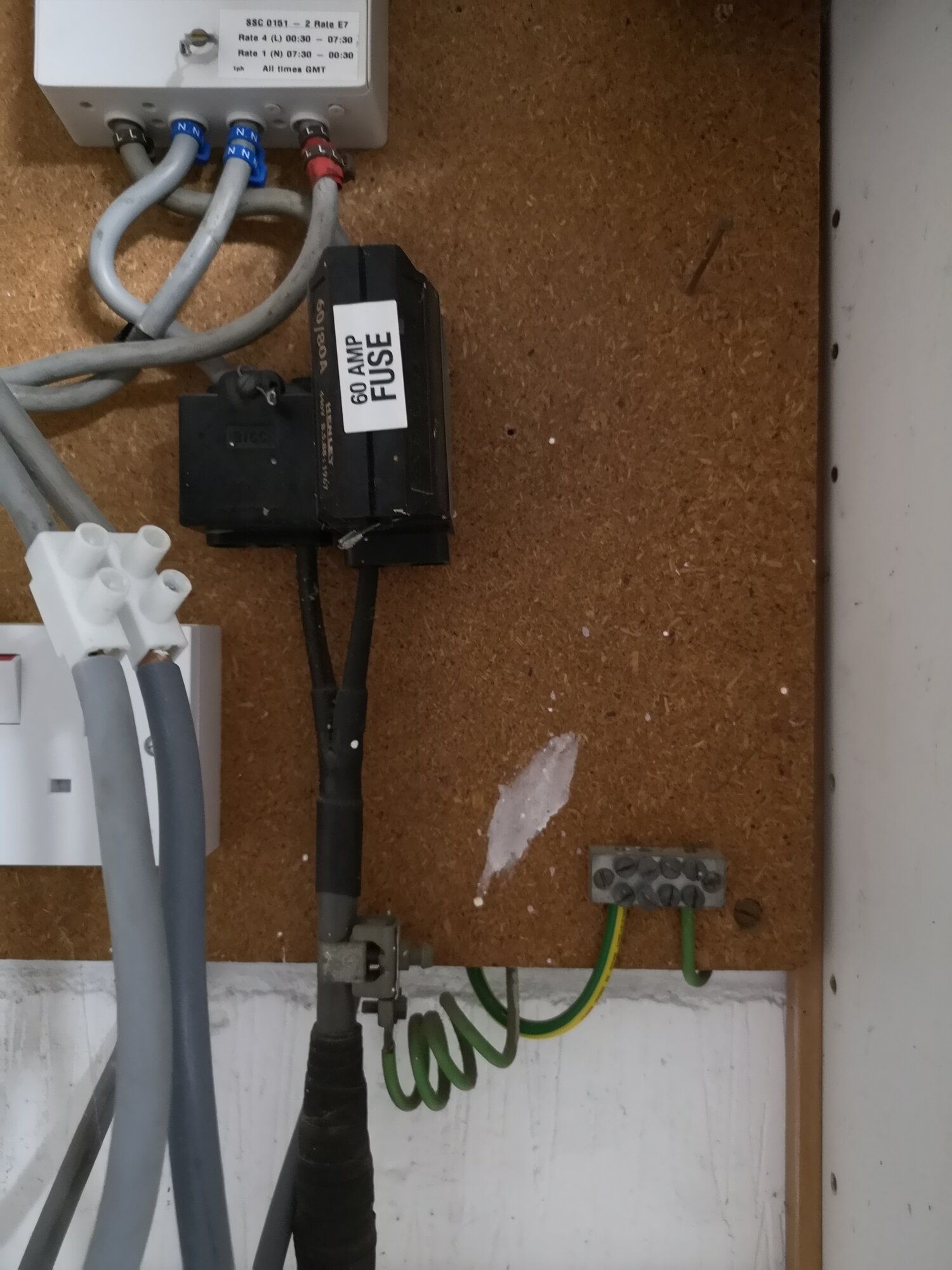
OK - all comments above apply! I suggest you get those tails sorted out and an isolator fitted ASAP.

1) The earthing system appears to be TN-S. In the absence of a measured value, we will use 0.8Ω for the value of the external earth loop impedance, represented by Ze. This value is important as it forms part of the loop impedance through which a fault current will pass ( represented by Zs) and we need to ensure that the total impedance of that loop is not so high that the fault protection device will not operate within the time required in the regulations, which is 0.4 sec. (reg 411.3.2.2 table 41.1). 0.8Ω is the maximum value of Ze declared by the supplier for TN-S supplies.

2) 14m - we will use this value later to calculate Zs and voltage drop (Vd). At this point, I simply note that this is very short and very unlikely to have any impact on the cable size selection, for reasons that will shortly become apparent.

3) Here we come to the crux of the matter, relating directly to the first three posts in this thread. All cables have resistance, and when a current flows through a cable, energy is released as heat, which increases the temperature of the cable. This heat is dissipated into the surroundings and the temperature of the cable increases until the rate of energy loss to the surroundings is equal to the rate of energy released as heat generated by the current passing through the cable. The thicker the cable, the lower the resistance and thus the lower power lost as heat (P=I²R).

The cables normally used for domestic installations are rated to 70C. If the cable temperature rises above that the cable may be damaged and may eventually cause a fire or other hazard.

Now, the rate that a cable can lose heat to its surroundings depends on the thermal conductivity of those surroundings. The regulations describe 120 different methods of installing a cable (table 4A2) and other tables allow us to determine the current carrying capacity (CCC) of different types and sizes of cable for each of those Installation Methods. We have to select the cable size based on the worst case for the installation methods that will be used.

In this case, the OP states that the cable will be installed as follows:

1) "in some conduit"

2) "into ceiling void where there is some rockwool type insulation so will be attached to joist". The OP is unsure are this point if the insulation thickness will be <=100mm or > 100mm, so I will look at both options.

3) "into a chased concrete block wall"

These equate to installation ref. method B, method 100 or 101 and ref. method C respectively. We now need to check in table 4D2A (for B) and 4D5 (for 100, 101 and C) to find the size of cable required for a 32A circuit.

For 6mm², the CCCs are as follows:

Ref method B: 38A
Method 100: 34A
Method 101: 27A
Ref method C: 47A

So, 6mm² will suffice, subject to checks for Zs and Vd, so long as the insulation thickness in the ceiling is <=100mm (method 100). If the insulation is >100mm (method 101) then 6mm² cannot be used.

Let us now select the cable for method 101. Again, from table 4D5 we can see that the next size up, 10mm², has a method 101 CCC of 36A, which will suffice. Since this is the worst case, we don't need to look at the other methods.

All that remains now is to check for Vd and Zs. In this case, since, with a 15m run and cables >=6mm², I know that this will not be an issue and as my fingers are getting tired I leave this as an exercise for the reader.

NOTE: to others - rather than clutter up this string with endless discussions of no help to the OP, as so often happens, if you spot any errors in the above, please send me a private message and I will correct them and give you a credit.
 
Last edited:

DIYnot Local

Staff member

If you need to find a tradesperson to get your job done, please try our local search below, or if you are doing it yourself you can find suppliers local to you.

Select the supplier or trade you require, enter your location to begin your search.


Are you a trade or supplier? You can create your listing free at DIYnot Local

 
Sponsored Links
Back
Top