Core drilling hole in supporting pillar?

And presumably there was some existing constraint forcing you to have the conservatory ceiling so low and flush with the frame head? Otherwise the whole lot would normally be raised.
Probably the slope of the roof that comes down above the lintel. To raise the lintel and conservatory ceiling component would mean the whole lot sticking up proud of the sloping roof. As it was they had to remove two rows of roof tiles to butt the conservatory join against the level where the fascia used to be.

Also, where the conservatory joins to the house wall it also connects to a flat roof existing extension - that may have dictated the height of the overall thing.
 
Last edited:
Sponsored Links
FD60915.JPG


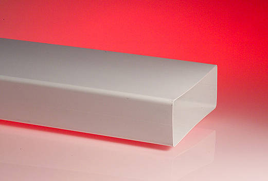
This on it's side only would only need a 90mm notch out of the side of the pier.
 
FD60915.JPG


This on it's side only would only need a 90mm notch out of the side of the pier.

Yes, that was suggested earlier in trhe thread and looks the way to go. The only thing is it means I have to core drill 4 x 91mm holes and I hate core drilling! I have diamond drills but that is still probably 45 mins per hole and a lot of aching arm muscles!
 
Last edited:
Can you get on the roof, lift a few tiles and membrane to establish exactly where the steel end is, and look for options to go around it. If you have good access from above you might find it's safe to slice a diagonal corner off the top right of the steel without compromising it.
 
Sponsored Links
Can you get on the roof, lift a few tiles and membrane to establish exactly where the steel end is, and look for options to go around it. If you have good access from above you might find it's safe to slice a diagonal corner off the top right of the steel without compromising it.

Possibly. The "simplest" route would be to go vertically up from next to the right side of the beam. I haven't measured it but I think that would come up through the roof tiles (rather than the floor of the room above which starts further to the right).

It would need a soil pipe roof kit, cowl, condensation drain etc and that is probably beyond my diy skills!
 
If this is a bungalow, isn't there an eaves void above that area where you can take the vent vertically?
 
If its been designed as a 300 pier then it needs to be one all the way up.
Absolutely not.
It's perfectly possible for the pier to be 300 x 300 for - say - 3/4 of it's height, and then 200 x 300 for the top quarter.

It depends on the integral of the characteristic strength divided by the partial safety factor over the middle third. I think you are confusing
the bearing capacity with the unfactored live load, which as you know must not exceed 10% of the factored dead load.
You are also not taking into account the reduced shear stress across the section immediately under the padstone, and how this impacts on deformation and long-term creep...........except on Tuesdays when it goes the other way.
Were you away when they did all this at college?
 
Last edited:
Absolutely not.
It's perfectly possible for the pier to be 300 x 300 for - say - 3/4 of it's height, and then 200 x 300 for the top quarter.

It depends on the integral of the characteristic strength divided by the partial safety factor over the middle third. I think you are confusing
the bearing capacity with the unfactored live load, which as you know must not exceed 10% of the factored dead load.
You are also not taking into account the reduced shear stress across the section immediately under the padstone, and how this impacts on deformation and long-term creep...........except on Tuesdays when it goes the other way.
Were you away when they did all this at college?
You seem to be referring to some hypothetical pier in Tonyland. That was on the Wednesday semester at Lego Uni. I attended Friday afternoons.

I'm taking about a pier 2.3m high in some bloke's bungalow holding up a 3m beam and a bit of roof.

I do like the concept of an attached pier in someones kitchen actually needing to be wider at the bottom and then stepped in 3/4 of the way up.
 
If this is a bungalow, isn't there an eaves void above that area where you can take the vent vertically?
The only way to access that area is to lift roof tiles and cut through the membrane and I'm not sure I want to do that (or can even access it easily now that the conservatory is "in the way").
 
I do like the concept of an attached pier in someones kitchen actually needing to be wider at the bottom and then stepped in 3/4 of the way up.

Seriously, it can in theory be done like that, though in practice it would be pointless.

There is a similar analogy in beams; in a simply-supported steel beam carrying a uniform load, the bending stress is greatest in the middle, and tails off to zero at the supports (this is why you see the parabolicic shape of bending moment diagrams).

Because the bending stress is greatest in the middle of the span, that's where most of the metal needs to be, but in practice it would be expensive to fabricate beams with thicker flanges in the middle but with thinner flanges towards the ends, just to save metal.

But you can often see this principle used on older steel railway bridges made of built-up beams, where the top and bottom flanges are built up with plates riveted together. The flanges (where all the bending stress is taken) are thicker in the middle but thin off towards the supports.
 
The only way to access that area is to lift roof tiles and cut through the membrane and I'm not sure I want to do that (or can even access it easily now that the conservatory is "in the way").
If you can get to it, that would be the much simpler, practical and better looking option - up through the floor and out through a tile terminal.

Lifting tiles, cuting the membrane and sealing everything back up again is relatively easy.

Can't you see the eaves void from the room above?
 
Seriously, it can in theory be done like that, though in practice it would be pointless.

There is a similar analogy in beams; in a simply-supported steel beam carrying a uniform load, the bending stress is greatest in the middle, and tails off to zero at the supports (this is why you see the parabolicic shape of bending moment diagrams).

Because the bending stress is greatest in the middle of the span, that's where most of the metal needs to be, but in practice it would be expensive to fabricate beams with thicker flanges in the middle but with thinner flanges towards the ends, just to save metal.

But you can often see this principle used on older steel railway bridges made of built-up beams, where the top and bottom flanges are built up with plates riveted together. The flanges (where all the bending stress is taken) are thicker in the middle but thin off towards the supports.
I know you know what you are talking about. (y) I was just looking at it from a less technical perspective

Send me your prospectus for a 1/2 day refresher.
 
That's where I would run it. Tile vent, or roof terminal and lead slate on the roof.
 

DIYnot Local

Staff member

If you need to find a tradesperson to get your job done, please try our local search below, or if you are doing it yourself you can find suppliers local to you.

Select the supplier or trade you require, enter your location to begin your search.


Are you a trade or supplier? You can create your listing free at DIYnot Local

 
Sponsored Links
Back
Top