
It was for 6 flats, I do recall it being a bit strange, at first i thought it was unearthed pyro, hears another picThat had struck me as well - it's not the sort of thing you would expect to see if they weren't done by the same person (or at least, people trained to work in the same way).
But looking back at the original photo, there's something else ...
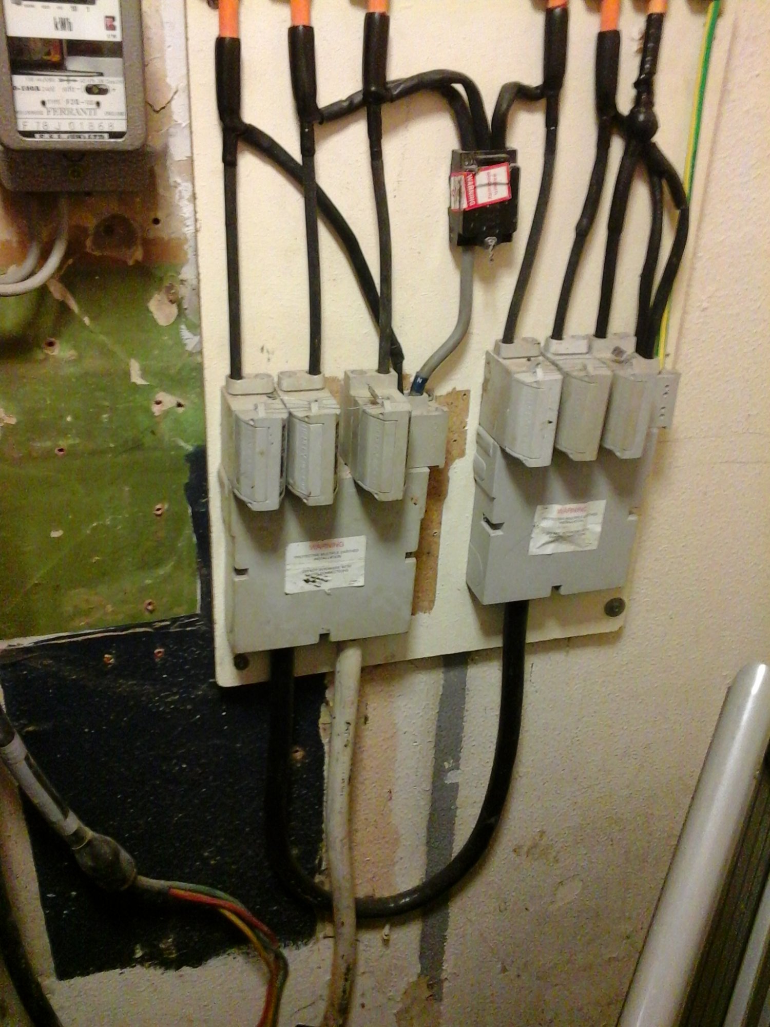
Anyone see any earth cable there ? So either it's a TT supply downstream, or it's still using a PEN. I wonder if there's more to this - what is the supply feeding ? Could it be something where the DNO is responsible for connecting a supply to something ? Or could it be something like street lighting which I suspect has different rules again ?
Is it me, or does it look like the neutral for one phase of the right hand head comes from the left hand service ? it looks a lot like 2off 3 phase supplies going off to 6off single phase meters. Also, there's only one earth which comes off the right hand head.
Perhaps it's 1off 3 phase supply split to 6off supply fuses - can't tell without seeing what's cut off below the photo.

You are using an out of date browser. It may not display this or other websites correctly.
You should upgrade or use an alternative browser.
You should upgrade or use an alternative browser.
Correct use of Split Con?
- Thread starter SUNRAY
- Start date
We seem to see a lot of meters fitted in commercial premises for phone masts lately, could it be for one of them
But if downstream is TT, then it's not a PEN, just a neutral - though I suppose from the DNO's PoV they can't know what the customer might do in the future. Earth fault current always goes through the meter - just normally through the live, and thus through the metering gubbins. I do get your point though - it's another potential point of failure for the earthing.Only if, as you have postulated, a PEN is going through the meter. With the 'usual arrangement' the earth fault path bypasses the meter by virtue of the installation's earthing conductor being derived from the PEN upstream of the meter.
Hmm, does look like separate supplies - a bit naughty mixing the neutrals like that. My guess is that each flat has it's own cutout, so the cables in that picture are the DNO's property and the service heads are just a convenient way of splitting the incoming cable - might even have links rather than fuses in them.It was for 6 flats, I do recall it being a bit strange, at first i thought it was unearthed pyro, hears another pic
That was my point - that in the 'usual' situation, of splitting the PEN into N and E, the 'E' part of it does not go through the meter.But if downstream is TT, then it's not a PEN, just a neutral...
Yes, sorry, I wasn't clear enough. I meant (at least, was thinking of) that the 'earth' half of the earth-fault loop didn't go through the meter if the PEN didn't. However, as you imply, that's probably much less for anyone to worry about than the (unavopidable) fact that any earth fault current will be going through the L side of the meter, anywhere.Earth fault current always goes through the meter - just normally through the live, and thus through the metering gubbins.
In any event, there may be a 'simpler', regulatory, reason why a PEN is not 'allowed' to go through a meter. I'm not totally sure (even having looked at the regs) exactly where "a consumer's installation" is deemed to start, but I would presume that it cannot be any further downstream than the output terminals of the meter. Hence, if what came out of the meter were a PEN, that would be in violation of both BS7671 and ESQCR.
Having said all that, as you go on to say ....
If the DNO have not provided a TN-C-S earth (i.e. haven't connected the installation's earthing conductor to the PEN upstream of the meter - or, at least, provided provision for that to be done), then what will go through the meter is 'just the neutral' - but it could become a ('not allowed') PEN if someone (not the DNO) subsequently decided to derive the installation's earthing from the post-meter neutral......though I suppose from the DNO's PoV they can't know what the customer might do in the future.
Kind Regards, John
Indeed - it is, at the very least, potentially confusing (and would probably have been less so had the neutrals from all three of the outgoing circuits from the RH cutout been derived from the LH cutout).Hmm, does look like separate supplies - a bit naughty mixing the neutrals like that. My guess is that each flat has it's own cutout, so the cables in that picture are the DNO's property and the service heads are just a convenient way of splitting the incoming cable - might even have links rather than fuses in them.
However, even if the cutouts do have fuses in them, the neutrals of the two cutouts will be directly connected by the linking cable - so I suppose that (cable CSA allowing), electrically speaking there would be nothing wrong with what has seemingly been done.
Kind Regards, John
I think we're violently in agreement here. But I think you missed my point that if the supply (or rather, what's downstream) is TT, then any earth fault current wouldn't be going through the neutral connection - regardless of where any PEN got split into N & E. But I agree, it doesn't look a very good arrangement - at least in the absence of more information about the installation.That was my point - that in the 'usual' situation, of splitting the PEN into N and E, the 'E' part of it does not go through the meter.
Indeed, which is why it's probably rather fruitless to debate further in the absence of more information on what's downstream - I would imagine "not a standard supply as we are used to it".In any event, there may be a 'simpler', regulatory, reason why a PEN is not 'allowed' to go through a meter. I'm not totally sure (even having looked at the regs) exactly where "a consumer's installation" is deemed to start, but I would presume that it cannot be any further downstream than the output terminals of the meter. Hence, if what came out of the meter were a PEN, that would be in violation of both BS7671 and ESQCR.
Indeed.Having said all that, as you go on to say ....
If the DNO have not provided a TN-C-S earth (i.e. haven't connected the installation's earthing conductor to the PEN upstream of the meter - or, at least, provided provision for that to be done), then what will go through the meter is 'just the neutral' - but it could become a ('not allowed') PEN if someone (not the DNO) subsequently decided to derive the installation's earthing from the post-meter neutral.
Linking cable ? Do you mean the point where the supply cable neutrals get connected to one common neutral in the distribution network ?Indeed - it is, at the very least, potentially confusing (and would probably have been less so had the neutrals from all three of the outgoing circuits from the RH cutout been derived from the LH cutout).
However, even if the cutouts do have fuses in them, the neutrals of the two cutouts will be directly connected by the linking cable - so I suppose that (cable CSA allowing), electrically speaking there would be nothing wrong with what has seemingly been done.
Apart from potential issues around neutral currents (which I suspect aren't going to be significant in this situation), what happens in one of the cables gets cut ? If it's the left hand cable, then 3 flats lose their supply, and another loses it's neutral. If it's the right hand cable, then 3 flats lose their supply - so no great deal.
But in the latter case, do the other 3 flats also lose their earth ? I see there's one earth cable coming from the right hand service head - if that's the TN-C-S earth for all the flats then cutting one cable removes the earth for all 6 of them
 But if the TN-C-S earths are derived at the individual service heads in the flats, then cutting the left hand cable not only removes supply from 4 flats, but also leaves a situation where any loads in one of the flats (the one with the cross-connected neutral) will apply 240V to the earths of those 4 flats
While there is always scope for losing a neutral while phase(s) remain connected - this seems to be a case of having created a higher risk of that by splitting phase and neutral between two cables that may be following different paths. Hard to tell, but it looks like there may be a mix of old and new there - left hand looks like old (painted ?) cable and new service head (outline of old head in the paint), right hand looks like new cable and new head. Normally if the proverbial digger bucket goes through a cable, it stands a good chance of breaking all the conductors - relatively safe for the people downstream. But if it breaks one of the two cables then it's created the risk described.
Again, a case of "more info needed". But IMO it would have been significantly safer had the fitter used two Henley blocks - one for each side.
I don't think I missed anything. If the connected installation was constituted as TT, then there surely would not be any 'PEN' - it would simply be a neutral?I think we're violently in agreement here. But I think you missed my point that if the supply (or rather, what's downstream) is TT, then any earth fault current wouldn't be going through the neutral connection - regardless of where any PEN got split into N & E.
Well, as I said, if what comes out of the meter is used as a PEN (i.e. split into N and E downstream of the meter to derive an 'earth'), then I don't think there would be any need for 'debate' - since the arrangement would then be in violation of both BS7671 and (probably more to the point) ESQCR.Indeed, which is why it's probably rather fruitless to debate further in the absence of more information on what's downstream -
I think perhaps one potential confusion results from the fact that a supply which has been PMEd does not necessarily have to be used s TN-C-S - and if it isn't used as TN-C-S, then it isn't really TN-C-S (i.e. as used, doesn't have a PEN). In other words, whilst 'PME' is an inherent feature of the external network, TN-C-S (or, come to that, TN-S) is simply a description of how the supply 'is used'.
Are we talking about the same thing? I'm talking about the arrangement Ricky showed in post #16 in which there is seemingly an incoming (grey) feed to the LH cutout and a (black) 'linking cable' between cutouts linking the RH cutout to that supply. I was talking about that (black) 'linking cable', cutting of which would totally remove supply from everything supplied from the RH cutout (leaving just one of those circuits with a connection to the incoming neutral) and, as far as I can see, would have no effect on things supplied by the LH cutout.Linking cable ? Do you mean the point where the supply cable neutrals get connected to one common neutral in the distribution network ?
Kind REgards, John
Indeed it does seem like I've been talking about something different. I hadn't seen that the RH supply was looped off the LH oneAre we talking about the same thing? I'm talking about the arrangement Ricky showed in post #16 in which there is seemingly an incoming (grey) feed to the LH cutout and a (black) 'linking cable' between cutouts linking the RH cutout to that supply.

Ah - that explains my confusion as regards what you wrote!Indeed it does seem like I've been talking about something different. I hadn't seen that the RH supply was looped off the LH one
Kind Regards, John
DIYnot Local
Staff member
If you need to find a tradesperson to get your job done, please try our local search below, or if you are doing it yourself you can find suppliers local to you.
Select the supplier or trade you require, enter your location to begin your search.
Please select a service and enter a location to continue...
Are you a trade or supplier? You can create your listing free at DIYnot Local