Door Entry Phone - again

Joined
10 Mar 2008
Messages
39
Reaction score
0
Location
Essex
Country
United Kingdom
I have just bought a new single button door entry phone for my flat to replace the old one. I bought it from www.entryphone.co.uk and it is a model 201.

I have wired in the new phone but when someone presses the button outside it does not ring inside, it only rings when you pick up the reciever.

This is driving me mad so i would really appreciate some help.

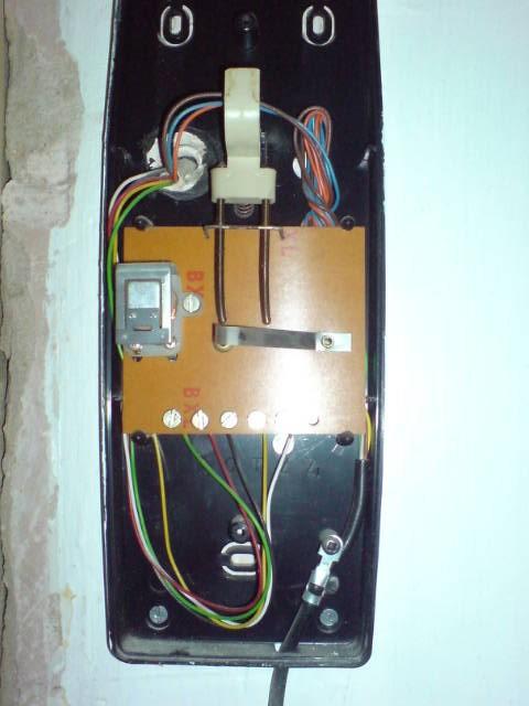
This is a picture of the phone that i have removed (no make or model on it though)


This is a picture of how it was wired up


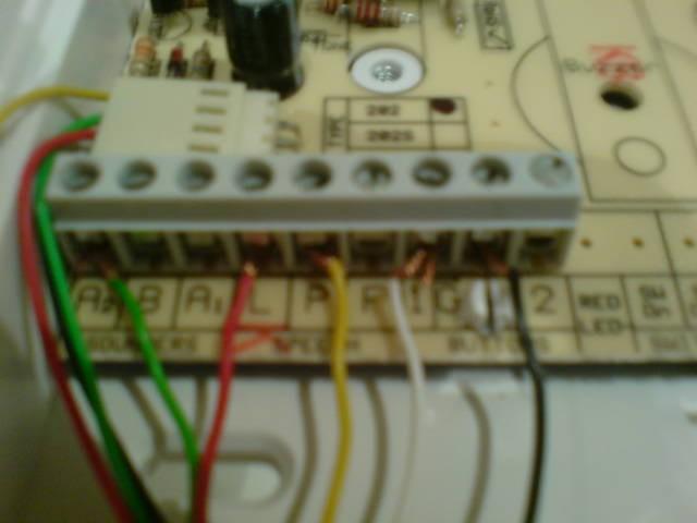
This is a picture of how the new phone is wired up


These are instructions given by the company


http://www.entryphone.co.uk/pdf/phones.pdf

Thanks

Phil
 
Sponsored Links
Not sure why you haven't just carried on from the last thread. Weren't we waiting for some better pictures?

Please write down the connections and post details, beacuse those pictures make it impossible to see what is what !

So old phone wiring

Green XXXXX (marker on old phone circuit board)
Red XXXXX (marker on old phone circuit board)
Black XXXXX (marker on old phone circuit board)
Yellow XXXXX (marker on old phone circuit board)
White XXXXX (marker on old phone circuit board)

Then positions available and used on new phone

Green ???????????
Red ???????????
Black ???????????
Yellow ???????????
White ???????????

It would also help if you trace the cable back from the phone to the power unit. In the power unit the cable will terminate on to a powers supply and a circuit board.

Please confirm what the

Green ???????????
Red ???????????
Black ???????????
Yellow ???????????
White ???????????

terminate on to.
 
entryphone will supply diagrams for connections for most other makes
if you can find the make of the old system they will give you the corresponding connections give them a call they are normally very helpful
 
you should folow instructions for BELL (BSTL) as that's the make of your old handset. hope this helps
 
Sponsored Links
from the instructions, and the somewhat still unclear picture of the terminations.. ( need top down so we can see the letters ), it looks as though the terminations go, from left to right...

A2 / B / A1 / L / P / R / 1 / G / 2.

is this correct?

if so then i think you need a wire connecting B and G together ( and F, but you don't seem to have one of those.. )

this would be the ground for the buzzer that it is missing.. it sounds like it currently feeds back through the "on hook" switch when it's made..
 

DIYnot Local

Staff member

If you need to find a tradesperson to get your job done, please try our local search below, or if you are doing it yourself you can find suppliers local to you.

Select the supplier or trade you require, enter your location to begin your search.


Are you a trade or supplier? You can create your listing free at DIYnot Local

 
Back
Top