Drayton SCR Wiring Correct?

Joined
15 Sep 2013
Messages
6
Reaction score
0
Location
Bradford
Country
United Kingdom
Hi All,

I just bought a new house which has a Flexicon 30cx boiler along with a Drayton SCR/3RF

I noticed that the central heating would always be 'on' regardless of the demand from the SCR receiver.

I eventually did some research and thought I had found the problem (my SCR wasn't clcking when demand was applied so have replaced the SCR now).

Now I get a click when I demand heating on and off but the bouiler is still heating continuously.


I've now done some further reading and supposedly if the drayton SCR is not clicking the boiler shouldn't come on at all (not be on continuously). So What i think has happened is the previous owners made a 'quick fix' to the SCR/boiler wiring to override the SCR/RF unit. This would've allowed them to manually turn on/off the heating but not control it via the receiver unit.

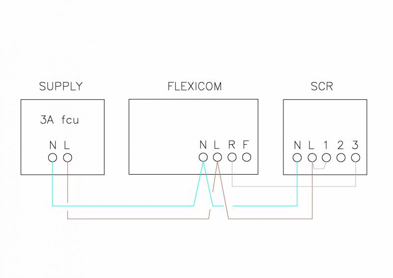
Does anyone know what the wiring behind the Drayton SCR should look like as it currently looks like this:


Checking the SCR manual I believe the wiring should be as follows (which differs from mine). I've attached it below:


Assuming the wiring was bodged to make the boiler work :

Current assumption is that connecting L and 1 is the same as L and R for the flexicon which permanently sets a heating demand and that I would have to get another bit of wire to bridge 1 to 2 and 3... but not entirely sure of this. Anyone can offer advice?[/url]

An example wiring diagram for my boiler is shown here:


I'm assuming the bottom tieing is so that R can be driven by the demand signal. It would make sense that R (on the flexicon) drives the on/off signal such that if it is linked with the demands they will drive then on/off state of R. It may be that L and 1 have to be linked together in addition to 3.
 
Sponsored Links
Remove the link between L and 1 and see what happens, that shouldn't be there according to your diagram.
 
Hi thanks for your replies. I did think about removing to loop between live and number 1, and this indeed did stop the boiler from firing up continuously but the digistat scr also couldn't turn on the heating.

Hence why my next thoughts were that probably two white wires existed one to connect 1 to 2 and 2 to 3 (connecting all of them to a common reference I'm guessing.

If i take the entire SCR off the wall for example the boiler will still fire up so it is simply the fact L and 1 are connected that means it will demand continuously.

I'm going to try and connect it per the drayton manual once i get an extra bit of wire (similar gauge of course). Pretty sure that will help. It makes sense as at the moment the drayton scr heating off is not connected.

I'm assuming the grey wire is the demand wire to the boiler. I've checked the 30cx manual and it indeed does only have two connections R and F.
 
Sponsored Links
I've updatd the first post with the wiring diagram from my 30cx. Think I understand it a bit more (maybe). L and R drive the on/off for boiler. Like a switch is L and R are shorted it will turn boiler on. L and R are currently connected so boiler will turn on constantly.

If R is connected also to the signal that drives ON/OFF the boiler then it will act like an additional switch for the reference driving ON/off the signal. Question is whether I need to bridge L,1 and 3 together.
 
I'm going to try and connect it per the drayton manual once i get an extra bit of wire (similar gauge of course)

Do you mean this?


If so, that doesn't show 1, 2, and 3 connected, it shows the internal connections which is basically a switch between 1 and 3. Trace the wires at both ends and connect it as per both of your diagrams.
 
If there is a link between L and R on the boiler, remove it.

Where does the white wire in T1 on SCR go? (not the link - that's obvious ;) )
 
Drawing below, showing the connections you require. (earth connections omitted for clarity)


I have no idea what the unidentified extra white wire on terminal 1 of the SCR is. But I wouldn't be surprised if was connected to the 'F' terminal of the boiler. If so, the boiler will be thinking it's receiving a 'run' signal from a frost thermostat which will override the normal controls and cause the boiler to run continually.

Thank you very much you just confirmed my latest assumption. I had a chat with guys at work all day trying to figure out was going on. As you say they at the moment with the white cable connected (which is probably F) it continually drives the heating as it overrides the switching mechanism.

Took me a while to realise that essentially the boiler has two 'demands' one for a frost override and one for the normal return. As no Frost Thermostat is connected it just needs one wire and live connected to the common.

I do wonder if the RF kit ever worked if the wiring is like it is now as presumably wouldn't you have cut the white cable back? or at least insulate it?
 
As no Frost Thermostat is connected it just needs one wire and live connected to the common.
If you have the older Digistat RF3 (the user control is a square box about the same size as the SCR), there is a built in frost protection of 7C. This is the same as the overnight temp (moon). You can use the Select button to set the programmer to continuous overnight temperature. This would give you frost protection while you are away.

The later Digistat +3RF has automatic frost protection built in, so you don't have to remember to turn it on when you go away - all you do is turn the heating off. It turns the heating on if the temperature drops below 5C and then holds the house at 7C.
 
Thanks will keep that in mind for the frost protection mechanism :).

Cheers All.

Will let you all know if correcting the wiring works :).
 
Good news. I wired up per stem's suggestion and we are now back to wireless control :). So my detective activity has led to this.

1. Drayton SCR failed because of a faulty capacitor (common fault supposedly)
2. Old Owner hardwired switch on by connecting live to common closing the circuit.
3. I come along and fix the SCR with a new capacitor (bought off ebay for 3 quid)... then realise wiring is wrong
4. With your help I fix original wiring bodge so we are back to being controlled by SCR ...

= YAAY :) 3 quid repair :)
 

DIYnot Local

Staff member

If you need to find a tradesperson to get your job done, please try our local search below, or if you are doing it yourself you can find suppliers local to you.

Select the supplier or trade you require, enter your location to begin your search.


Are you a trade or supplier? You can create your listing free at DIYnot Local

 
Sponsored Links
Back
Top