First of all I need to point out that this is a difficult exercise. You need to be electrically competent to do this and understand what you are doing. If not engage the services of a professional.
There are different ways to wire these and the wire colours would have been chosen according to the personal preferences of the original installer, so a red wire in one installation may be a yellow in another. If you mix the wires up, then each wire will have to be traced individually back to its source to determine what it actually does. So you have been warned!!
On the other hand, if you are competent and understand what you are doing then it shouldn't be too difficult.
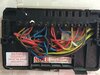
As you can see from the diagrams, the control wiring is the basically same, so the wires in the Potterton terminals N, L and 1 to 4.....
View attachment 203172
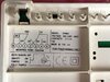
.....have exactly the same functions as the Honeywell terminals N, L and 1 to 4.
View attachment 203173
So the wires in these terminals are simply moved over from the terminal at the Potterton to the terminal that has exactly the same function at the Honeywell, thus:
Potterton N = Honeywell N
Potterton L = Honeywell L
Potterton 1 = Honeywell 1 HW off
Potterton 3 = Honeywell 3 HW on
Potterton 4 = Honeywell 4 CH on
Terminal 5 of the Potterton you can ignore because you can see in the diagram of the Honeywell that this electrical link to L is already made inside for you and doesn't require a separate terminal. So the two wires in 5 can be removed from the programmer but the they must remain connected together. [If you trace it you will see that effectively the brown wire is then connected to the L terminal]
View attachment 203176
The other Potterton terminals are just that, they function as a junction box, or wiring centre as
@ianmcd has explained, so have no connection to the actual programmer functions; so the two wires in 'B' need to be connected together in a separate new terminal, the two wires in 'C' also need to be connected together in a separate new terminal.
View attachment 203177
Earth wires also need to remain connected together in an earth terminal.
View attachment 203178
The usual problem is the space for the additional new connectors, so if there isn't one there already, I normally sink an electrical socket back box into the wall behind the programmer and put the new terminals in that safely out of the way. The new programmer is then mounted over it, and then only the wires required by the programmer brought through to it.
The back box will need an earth connection if it is made of metal.


")