Fused spur with remotely switched sockets

Joined
22 Jan 2023
Messages
8
Reaction score
0
Country
United Kingdom
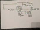
We currently have an outside light, on the lighting circuit, on a single switch, and a double socket on a spur from the ring circuit.

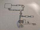
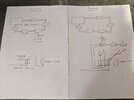
I'd like to replace the socket on the spur for a junction box (accessibility means I'll need the junction box), going into a fused spur with 2x double sockets and 2x single sockets. I need the 2x single sockets to be able to be individually and remotely switched where the current single light switch is.

I've included some magnificent artwork if anyone could confirm all looks ok.

I'll upgrade the switch to a 3 gang and 20amp but it will (hopefully) include the wiring for the garden light (on the lighting circuit) and the wiring for the 2x single sockets (on the mains fused spur).
 

Attachments

  • PXL_20230122_140837024.jpg
    PXL_20230122_140837024.jpg
    193.1 KB · Views: 75
Sponsored Links
1674397855781.png


Yes, that looks fine.

Obviously all the sockets must be connected to the load side of the FCU therefore you don't need two cables from FCU to 'c' and 'd'.
 
Sponsored Links
It just switches the Neutral as well (unless you don't connect it) so it will be wired the same as the Line(live).
 
It just switches the Neutral as well (unless you don't connect it) so it will be wired the same as the Line(live).
Ok so that's good for the 2x switches for the 2x single sockets but will that still work for the third switch - the one on the lighting circuit for the garden light - I can only access the wire already there for that (the live&switched live).

Sorry about all this
 
- the one on the lighting circuit for the garden light - I can only access the wire already there for that (the live&switched live).
The way you have drawn it in your first diagram it is also likely to be Line(live) and Neutral.

As in the second diagram doesn't really make sense.
 
The way you have drawn it in your first diagram it is also likely to be Line(live) and Neutral.

As in the second diagram doesn't really make sense.
Ok I'll have to have a look first. Thanks again for all your help
 
Ok I'll have to have a look first. Thanks again for all your help
Up at silly o'clock for work .

The current light switch has live & switched-live leading to the outside light that is wired the same as a ceiling rose with the loop but it's the final light on the circuit. I've also found a grid switch that can be set up with 2x double pole switches and 1x one way light switch.

So... (fingers crossed) .... Is the attached diagram all ok?
 

Attachments

  • PXL_20230123_034352287.jpg
    PXL_20230123_034352287.jpg
    189.8 KB · Views: 46
Yes, that is all fine, but - the light circuit is a different layout than the your first diagram.
Perfect, thanks yet again.

Yes, as I am using the new 3 gang switch for the garden light in exactly the same way as it is now in the 1 gang 1 way one, I (over)simplified that part just to show that was on the lighting circuit. The main headache was everything after the FCU on the new sockets with switches.

I'd better crack on
 

DIYnot Local

Staff member

If you need to find a tradesperson to get your job done, please try our local search below, or if you are doing it yourself you can find suppliers local to you.

Select the supplier or trade you require, enter your location to begin your search.


Are you a trade or supplier? You can create your listing free at DIYnot Local

 
Sponsored Links
Back
Top