• Looking for a smarter way to manage your heating this winter? We’ve been testing the new Aqara Radiator Thermostat W600 to see how quiet, accurate and easy it is to use around the home. Click here read our review.

Garage Door - Trying to Add Relay, but Getting Strange Results

Joined
22 Feb 2025
Messages
2
Reaction score
0
Country
United Kingdom
Hi all,

First post on here. I am currently having issues trying to wire up a relay for a Garage Door. I can only get the door controls to respond when I press both buttons on at the same time. Below are the details of the relay, garage door PCB and the wiring. If anyone has any ideas, or can point me as to where I am going wrong, it would be much appreciated.

Garage Door: Rollertec v5
- Fitters Handbook (SWS) - LINK
Relay: Shelly Plus 2PM Gen 3
- Vendor specification page - LINK
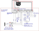
My Wiring
1740239170271.png
 

Attachments

  • 1740238830615.png
    1740238830615.png
    841.5 KB · Views: 57
The shelly device has 230V AC outputs to drive a motor directly.
The terminals on the controller are intended to be connected to a switch.
Shoving 230V AC in there isn't going to work as intended, and could easily damage the controller.
 
Looks like it's just supposed to be a link, you might be putting voltage on it where it doesn't want to be.
 
What are you hoping the Shelly to do? You don't appear to be used the switched contacts.
 
You don't appear to be used the switched contacts.
O1 and O2 are the switched 230V outputs.
S1 and S2 are for the connection of switches so that any normal switch can be used to control the connected devices in addition to the app and other wifi controls..
 
There are 3 issues that I foresee:

1. As Flameport has already mentioned the Rollertec indicates dry contacts shoud be used and connecting mains to any point of those 3 terminals is potentially troublesome, even destructive.
However if the common terminal is permanent live it shouldn't cause a problem: If you have a multimeter and know how to use it safely and properly you can easily perform tests to find out. If it does prove to be full live on T14 the nicer way of wiring is this
1740258892252.png


If T14 is not at mains potential you will have to isolate with a couple of relays
1740261563353.png


2. I recall the requirement to only use momentary commands, I don't know if that is really true or if the Shelly can be configured for that.

3. I also recall having to 'Program' Rollertecs by operating a sequence of buttons to make them do what was required for window blinds but too far back to remember any sort of detail including which model. Therefore I don't know if that's relevant to this unit.
 
Thanks for all of the replies! Much appreciated. So:
1) I have a Shelly Unit with Dry Contacts, so I will swap out: Shelly 1L v2. I did try this first, but may have wired up wrong.
2) I did use the Shelly 2PM originally to control the motors directly, but realised that without a sensor connected to the shelly switch port, this would drive the motor until it the system stopped the unit: the sensor for the Rollertec doesn't seem to stop the Shelly. I thought it would by removing the common interface connection... I probably misunderstood this.
3) The Shelly units can control the time the button is pushed, so a momentary touch can be configured.
4) Looking at the Rollertec as the door opens up and down, it does seem to have different contact combinations working to do different operations, so you are probably correct: you can see through a plastic cover the three contacts that connect to move the door.

Actions I Will Take
1) I will swap to the Shelly 1L v2 and test the dry contacts on that: FYI, this was what I tried with first, but I must have done something wrong.
2) I will test with a multimeter - as recommended - to see if the common is a constant Live

Thanks again! I will update once I have had a chance to test!
 
I've spoken with a friend who has a Rollertec PCB built into his up and over door motor however he guesses it's 10 years old and thinks it's a V2: He uses a single door bell style button connected as shown in the manual (so I assume T13 & T14) he has measured for you; 12Vdc across the button and doesn't light a neon screwdriver, that gives the 4 stage sequence shown on the drawing.
Image of a V2 board (Ignore the red circle):
1740315534439.jpeg


Clearly showing T14 T17 and T11 as 0V, I'll guess the V5 is similar, these are the best pictures of a V5 I've found and it looks like the markings may be similar.
1740315956926.jpeg

1740317839328.jpeg

I think it may be worth connectig a pair of switches just to test the Rollertec is doing what you expect / not damaged.
 

If you need to find a tradesperson to get your job done, please try our local search below, or if you are doing it yourself you can find suppliers local to you.

Select the supplier or trade you require, enter your location to begin your search.


Are you a trade or supplier? You can create your listing free at DIYnot Local

 
Back
Top