Help filling in Electrical Installation Certificate

Joined
1 Dec 2007
Messages
22
Reaction score
0
Location
Worcestershire
Country
United Kingdom
Hello,

I'm trying to fill in an EIC ready for the visit from the BCO.

I've got a few questions someone might be able to help with?

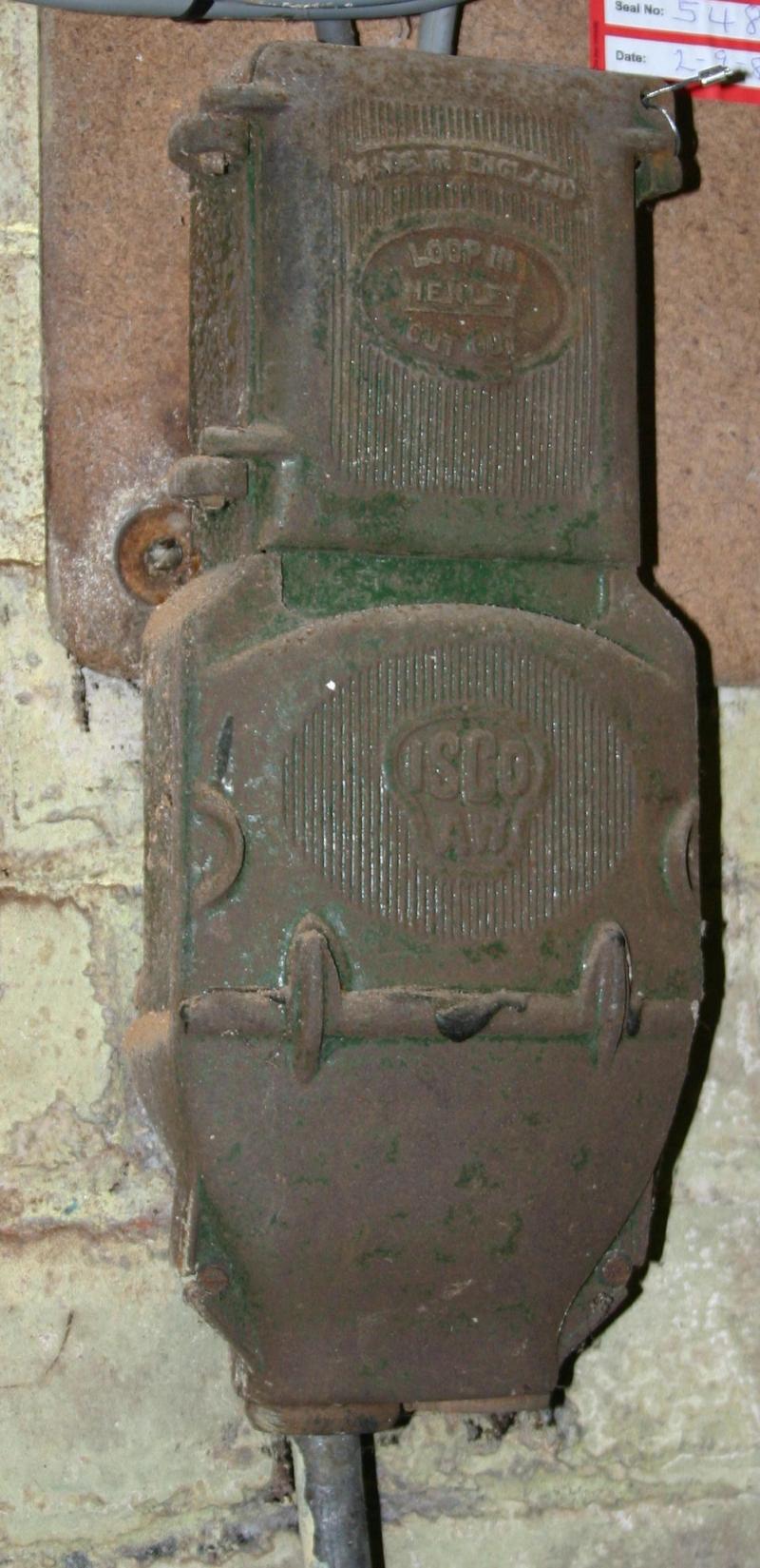
1) "Supply Protective Device Characteristics" - I presume this refers to the service fuse. I can't see any markings on it other than the manufacturer. How can I determine the type and rating? Can I assume BS1361, 60A?
2) PSC - I have a Robin KTS1610, which I now have instructions for, it describes measuring earth loop impedance, but not supply impedance. Can I use the 3 lead test set with green & black probes both connected to neutral at supply and red to live to measure supply impedance at the CSU? (Due regard to safety, GS38 fused probes etc.) Then calculate PSC from supply voltage? Is there another method I can use to get the PSC figure?

3) External Loop impedance. Is this measured with service bonds in place? (We are TT, I've already recorded earth electrode resistance individually on EIC page 2 using a loop test on isolated electrode.

4) Main Switch. I have a 100A main switch in the meter tails (mine not DNOs) in a separate box labelled "Main Switch" feeding 100mA S type in CSU. Should the 100A isolator be recorded as the main switch or the 100mA S-type that protects the whole system?

Thanks in advance
 
Sponsored Links
(We are TT, I've already recorded earth electrode resistance individually on EIC page 2 using a loop test on isolated electrode.

I’ll leave the answers to your questions to someone who knows better, however a point to note would be that service head is metal and thus should be earthed, as it belongs to the DNO they need to earth it, so either they need to supply an earth or change that cutout to a plastic one.
 
That's an interesting point. The DNO didn't mention it when he changed the tails over last month. He was wearing protective gloves and mask when he pulled the fuse, and mentioned it was in case he caught it on the metal case as it came out, so I assume the casing is earthed already. It's chargeable to go to PME, but for £98 I don't suppose they'd be pulling in a new supply cable so I guess there must be an earthed sheath already. I may be able to test it with a loop test to the casing but strictly speaking that's not my equipment.
 
I found answers to questions 2 and 3 in Guidance Note 3, but has anyone got any ideas about my incomer?

Sean
 
Sponsored Links
Well, you do it by enquiry. (Not that they will know - they told me I had a 100A fuse, and when I happened to see it, it turned out to be 60A.)
 
1) You cant know for sure, but cast iron cutouts tend to contain 30A BS3036 fuses.

2)You should carry out a loop reading L>E and L>N and record the highest value for PSC. (volts divided by resistance (loop impedence) equals current) My tester has a setting for L>N loop.

3)External loop impedence (Ze) is measured in isolation i.e. with all of the installation and all protective bonding etc. disconnected.

4)I would record the details of the first isolator.

Is this isolator in a PLASTIC enclosure?

IMO, you really would be best off spending that £98 on upgrading your supply to PME.

You will get a nice shiny new cutout with a lovely earth connection, and a better fuse than a BS3036 too :)

Not bad for under £100!
 
Thanks RF. Yes isolator is in plastic enclosure. Initially I kept it as TT as an RCD at the origin (split load 100mA S type + 30mA) meant I could be sure of meeting disconnection times on all circuits, including existing ones. If I went for PME is there any reason why I can't leave both the RCDs in place to save a redesign / recalculation of all circuits? Main bonds are all 10mm anyway thankfully.
 
Do you have a split-load board?

As for the supply fuse size & type, if I cannot determine it, I put "UNKNOWN".
 
I would certainly not advise a TT install with a metal cutout, either that cutout is not earthed at all or it is earthed to a different earth from your installation. Neither is safe IMO.
 
If I went for PME is there any reason why I can't leave both the RCDs in place to save a redesign / recalculation of all circuits? Main bonds are all 10mm anyway thankfully.

From table 54.8 (csa of main protective bond)

Note: Local distributor's network conditions may require a larger conductor

Dunno what the network are like round your way, but they cottoned on to this a couple of years ago round here and have been fleecing people with cancellation fee's for 10mm bonds ever since.

"Your electrician has installed the wrong earth wire, it would be dangerous for us to connect this, so you've wasted our time that'll be another £500 hur hur hur"[/u]
 

DIYnot Local

Staff member

If you need to find a tradesperson to get your job done, please try our local search below, or if you are doing it yourself you can find suppliers local to you.

Select the supplier or trade you require, enter your location to begin your search.


Are you a trade or supplier? You can create your listing free at DIYnot Local

 
Sponsored Links
Back
Top