I am contemplating upgrading my water and heating controls to the HIVE system. Currently I have a BG RC Plus Wireless Programmable Room Thermostat linked to a BG WR1 receiver to provide heating control. For water control I have a BG UT2 Single Channel Timeswitch/Controller. This is connected to a CS1 Tank Stat via wiring centre. The boiler is a conventional BG 330+. I have a separate water tank. There are two separate Drayton zone valves for water and heating. Lastly there is a pump. This system was installed by BG in 2011.
All systems worked as advertised and without problems.
I want to install a HIVE Dual Channel Receiver on the back plate where the WR1 is located. I am ok with the live, neutral and earth cables. I am ok with isolating the system when working on it...it has the necessary fuses and is easy to isolate.
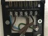
On the WR1 I have a Grey cable (Brown sleaving) connected to terminal 1 (COM) and a Black cable (Brown sleaving) connected to terminal 3 (HTG On). This appears to be wired in single channel configuration. The new Dual Channel HIVE has HTG On (4) and HTG Off (2). Photo attached.
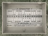
My question is what do I do with the Grey cable (COM) and is it needed? The Grey cable (COM) is terminated at the wiring centre, in this case terminal 3. There is a cable link in the wiring centre from terminal 3 to terminal 7 (HTG & HW Grey). Photo attached. As for the other WR1 I presume I simply move the Black cable on the backplate from the current terminal 3 in WR1 configuration to the HIVE configuration terminal 4 (HTG On)?
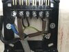
On the UT2 I have a Black wire with a Brown sleaving connected to terminal 3 (HW On). There appears to be a cable link between the live and terminal 1 (COM). Similar question is which cable(s) to connect to which terminal(s)? I presume I move the Black cable from terminal 3 in UT2 configuration to HIVE configuration terminal 3 (HW On). Photo attached.
Would appreciate any advice.
All systems worked as advertised and without problems.
I want to install a HIVE Dual Channel Receiver on the back plate where the WR1 is located. I am ok with the live, neutral and earth cables. I am ok with isolating the system when working on it...it has the necessary fuses and is easy to isolate.
On the WR1 I have a Grey cable (Brown sleaving) connected to terminal 1 (COM) and a Black cable (Brown sleaving) connected to terminal 3 (HTG On). This appears to be wired in single channel configuration. The new Dual Channel HIVE has HTG On (4) and HTG Off (2). Photo attached.
My question is what do I do with the Grey cable (COM) and is it needed? The Grey cable (COM) is terminated at the wiring centre, in this case terminal 3. There is a cable link in the wiring centre from terminal 3 to terminal 7 (HTG & HW Grey). Photo attached. As for the other WR1 I presume I simply move the Black cable on the backplate from the current terminal 3 in WR1 configuration to the HIVE configuration terminal 4 (HTG On)?
On the UT2 I have a Black wire with a Brown sleaving connected to terminal 3 (HW On). There appears to be a cable link between the live and terminal 1 (COM). Similar question is which cable(s) to connect to which terminal(s)? I presume I move the Black cable from terminal 3 in UT2 configuration to HIVE configuration terminal 3 (HW On). Photo attached.
Would appreciate any advice.