Hive wiring help

Joined
1 Mar 2023
Messages
2
Reaction score
1
Country
United Kingdom
I'm replacing my multi-zone Danfoss controllers with Hive, so far the downstairs Hive receiver is wired in and working well. I'm having a problem wiring in the Hive Single Channel receiver to replace a Danfoss TP 4000 for the upstairs zone.

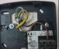
The TP 4000 is battery powered and has 2 connected wires to COM and N/O please see attached image.

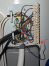
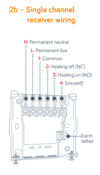
Hive wiring diagram attached for your information

I'm believe that I need to
  1. connect the brown COM cable to pin 1 on the Hive and create a bridging cable from 1 to L
  2. connect the black N/O cable to pin 3
  3. connect the spare grey to N
The problem I have is that the grey is not currently connected to anything at the other end, I've done a continuity check and traced the wire back to the main terminal, but I don't have any idea where to connect it.

Any help would be great! If you need any more info please ask.

Thanks
 

Attachments

  • TP4000 wiring.png
    TP4000 wiring.png
    1.2 MB · Views: 75
  • Tank Wiring Info.png
    Tank Wiring Info.png
    434.9 KB · Views: 63
  • Tank Wiring.png
    Tank Wiring.png
    455 KB · Views: 68
  • Hive wiring.png
    Hive wiring.png
    52.4 KB · Views: 68
Sponsored Links
Take the com to L on Hive and link to common at hive (terminal 1), the black wire goes to 3 and connect the grey to N at Hive and find a permanent neutral at the wiring center and connect the other end of grey there.
 
Done and done. All working well, thanks for your help
 
  • Thanks
Reactions: CBW

DIYnot Local

Staff member

If you need to find a tradesperson to get your job done, please try our local search below, or if you are doing it yourself you can find suppliers local to you.

Select the supplier or trade you require, enter your location to begin your search.


Are you a trade or supplier? You can create your listing free at DIYnot Local

 
Sponsored Links
Back
Top