- Joined
- 23 Nov 2019
- Messages
- 4
- Reaction score
- 0
- Country

I am sorry if I am duplicating posts here but had a look and cant quite see what I am after.
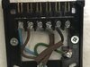
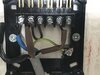
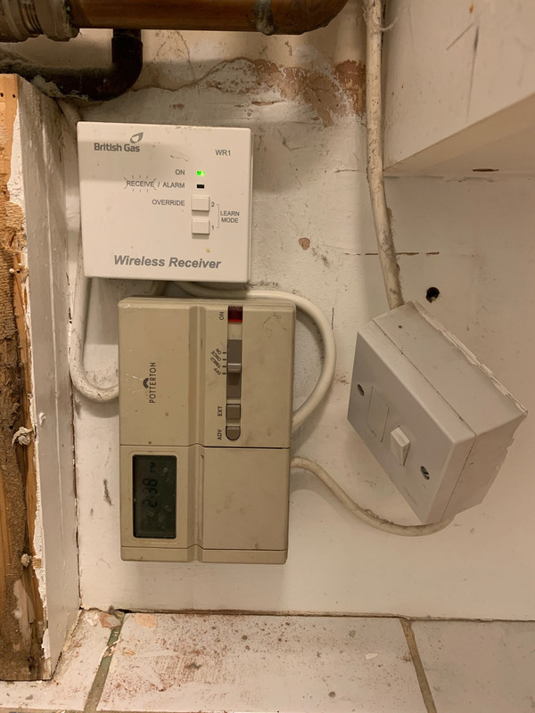
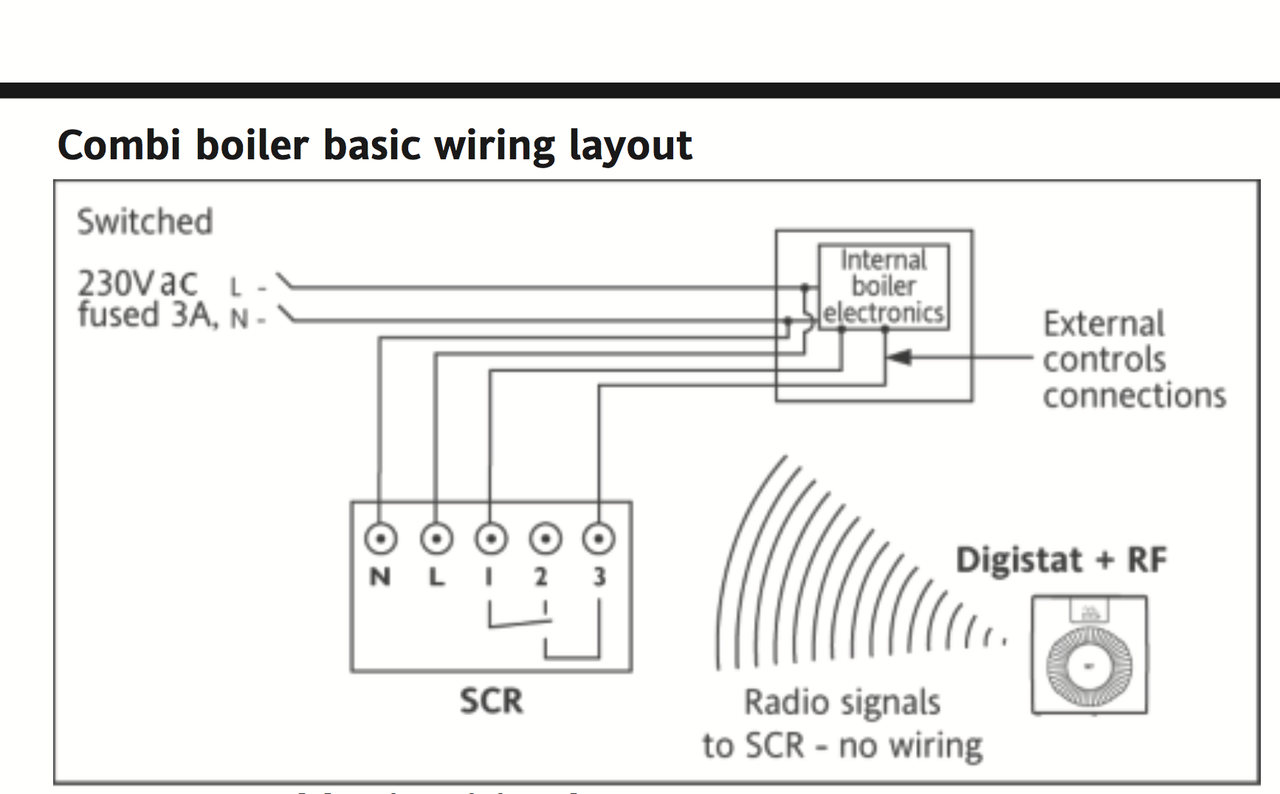
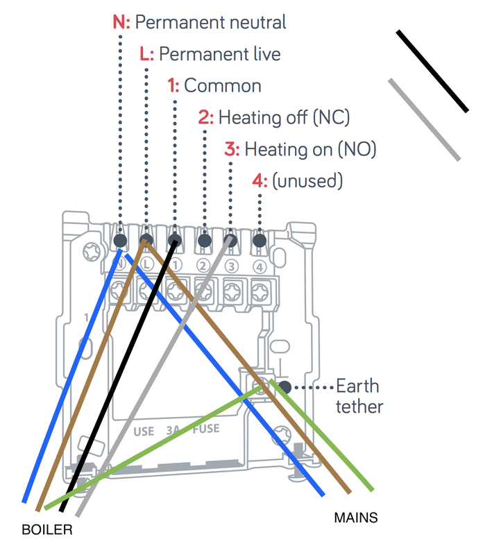
I have a old potterton E4000 series controller that I want to replace with a hive unit. I have a combi boiler (Potterton Promax Series). I have ordered the appropriate hive unit. Whats thrown me a bit is that I have an extra grey pair of cables coming out of the controller to boiler on connection 4 (which is marked as unused on Hive) Connection 2 on the backplane is currently unused, whereas its marked for use on Hive. I intend to remove the 4000 controller, so I will L/N/E from mains coming directly into the receiver rather than 4 pairs as I currently have now. I 'assume' that I will need to loop out from one to another somewhere but I am not sure.
Picture below

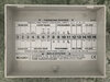
On the left is the diagram as Hive would like it, and on the right what I have in place with the WR1. I had a look at the Drayton site and none of the schematics there relate to what I have. (maybe they do but being a boiler numpty I am not clear what does w
could one of you kind folk give me some pointers? I tried to find the schematic for the controller but couldnt readily see one so I cant quite see how the functions need to be mapped.
thanks!
I have a old potterton E4000 series controller that I want to replace with a hive unit. I have a combi boiler (Potterton Promax Series). I have ordered the appropriate hive unit. Whats thrown me a bit is that I have an extra grey pair of cables coming out of the controller to boiler on connection 4 (which is marked as unused on Hive) Connection 2 on the backplane is currently unused, whereas its marked for use on Hive. I intend to remove the 4000 controller, so I will L/N/E from mains coming directly into the receiver rather than 4 pairs as I currently have now. I 'assume' that I will need to loop out from one to another somewhere but I am not sure.
Picture below
On the left is the diagram as Hive would like it, and on the right what I have in place with the WR1. I had a look at the Drayton site and none of the schematics there relate to what I have. (maybe they do but being a boiler numpty I am not clear what does w
could one of you kind folk give me some pointers? I tried to find the schematic for the controller but couldnt readily see one so I cant quite see how the functions need to be mapped.
thanks!
")
")