I would agree with you on the meaning of recommended.
If not necessary, why do they even recommend it?
Let's hope you are correct.
If not necessary, why do they even recommend it?
Let's hope you are correct.

I would agree with you on the meaning of recommended.
If not necessary, why do they even recommend it?
Let's hope you are correct.

just remove the Hive wiring for your CH and put a link in between the terminals and if your heating comes on then it is a control problem, if it doesnt you have damaged the boiler pcb


That's a bit strange because the wires at the thermostat are: Red / Yellow / Blue, and the wires at the boiler thermostat terminals are: Green & Yellow / Brown / Blue. Without being able to test or examine the wiring all I can guess is that either there is a junction box somewhere and maybe the position of the thermostat has been changed at some time and the cable extended, or perhaps there is also an external timeswitch also connected to the terminals. I assume that the thermostat you have shown does actually control the central heating.
As the photo you posted is of a single channel Hive receiver. [The original poster had a Dual Channel receiver, which is wired differently, so much of what has gone before won't apply to you]
Assuming that it's not too far away from the Hive thermostat, you can mount the Hive receiver nearer the boiler and connect it as below. Be careful when removing the old thermostat cable and make sure that it's 'dead' as we don't know for certain what's connected to the other end of it.
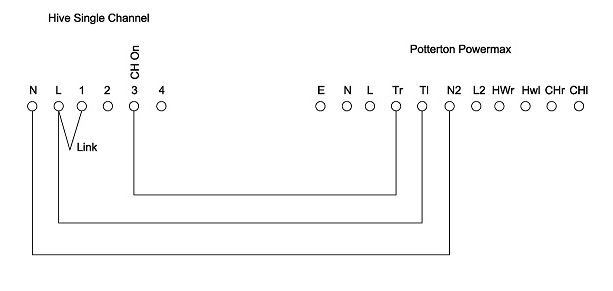
The yellow link is there for the connection of a remote programmer. It completes the heating circuit in its absence. As there isn't anything connected to it now, that indicates that your boiler has integral time control. [The purple link does the same thing for the hot water] Both links should remain in place.
Don't forget after installing the Hive to set the Heating time at the boiler programmer to be permanently 'on'
 . When I disconnected the old thermostat cable the wall lights no longer worked. These situations are very rare fortunately, but it makes me cautious when giving advice over a forum when I haven't been able to inspect the installation.
The reason I'm a little cautious is that over the years I have found some very odd thermostat installations. One where the thermostat as well as being wired to the boiler was also connected directly to the back of a socket on the wall behind. Not only was this without a fuse, but was unseen and meant that the cable was still live when the power to the boiler was turned off.
, swapped them around and customer was very happy, as was I - I love finding faults like that. If you need to find a tradesperson to get your job done, please try our local search below, or if you are doing it yourself you can find suppliers local to you.
Select the supplier or trade you require, enter your location to begin your search.
Are you a trade or supplier? You can create your listing free at DIYnot Local
