Honeywell Galaxy G2-12 wiring pirs/ contacts! ?

Joined
19 Apr 2012
Messages
25
Reaction score
0
Location
Staffordshire
Country
United Kingdom
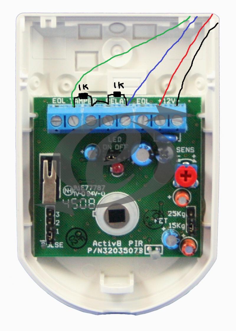
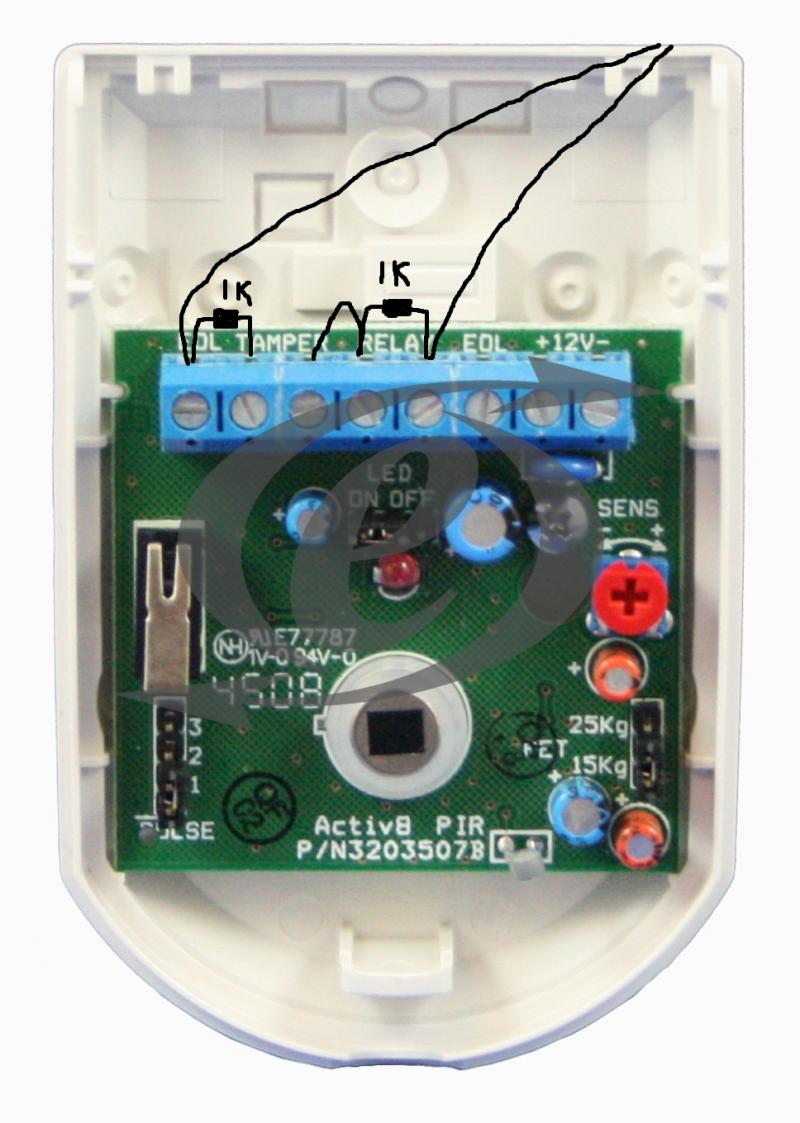
Hey everyone im new to this, Im just about to order the honeywell galaxy g2-12 the zones are set as double balanced and I think i understand how it works, ive done pic just to make sure im right, not to sure how to go about with putting 2 ressistors in 1 door contact??!? also the power for the pir's negitive (0v) is connected to the zone 0v is this correct? so the pir's relay connects to the 0v aswell as the negitive cable? or Am I wrong?
Thanks in Advance guys! :D
 
Sponsored Links
All wrong.

Have another go at it.

And buy a contact already with built in resistors, the packet is green.
 
Sponsored Links
you need to find out from your manual, first what resistors your alarm uses (mine uses different ones for eol and the tamper)

if yours is double eol, you will connect 4 wires to the pir (2 for power 2 for the pir/tamper)

once i see your manual for your alarm i will be able to help you further, give it a few days of you learning about this and you will soon get the hang of it.

http://www.strathand.com/cdata/24498/docs/1758647_2.pdf

thats the manual page 13 and 14. thanks again! :)
 
you need to find out from your manual, first what resistors your alarm uses (mine uses different ones for eol and the tamper)

if yours is double eol, you will connect 4 wires to the pir (2 for power 2 for the pir/tamper)

once i see your manual for your alarm i will be able to help you further, give it a few days of you learning about this and you will soon get the hang of it.

what about that pic? thanks!
 
the 2 alarm terminals need bridging with your resistor, then put one leg of another resistor into one alarm terminal, the other leg goes into one terminal of the tamper.

and you can avoid all that hassel of using pirs contacts etc with built in resistors.
 
Alarm/ Alarm Bridge with 1 1k resistor.

Alarm/Tamper bridge with the other 1k resistor.

Alarm leg 1 insert Red core
Tamper 2nd leg fit Yellow core.

Alarm.......Alarm......Tamper Tamper
 
Alarm/ Alarm Bridge with 1 1k resistor.

Alarm/Tamper bridge with the other 1k resistor.

Alarm leg 1 insert Red core
Tamper 2nd leg fit Yellow core.

Alarm.......Alarm......Tamper Tamper

Thanks for your help!! shouldn't I use the red cable for the 12v+? what do you reccomend colouring code wise, I thought back and red for power and blue and white for alarm/ tamper. How do i connect it up on the pannel? if your could do a diogram it would be very very helpful !! Im guessing pir power goes to + & - on the pannel, then alarm goes into one side of the zone, then the other into the 0v side of the zone, does it matter which way round the alarm connects on the pannel? thank you !!! :D :D
 
Use what colours you want.
Your correct in your assumption.
Not really. But it is neater to wire it consistently.
 
I'm having the same problem ,can someone check is that wiring ok ,
I found 2 ways doing not sure with one is right :
1st
byme10.jpg

2nd
byedan10.jpg

second picture using two zones is that right ?
Thanks
 
Use the wiring in the first picture if you have the default settings on the G2 series panel (double balanced. 1k closed 2k open).
 

DIYnot Local

Staff member

If you need to find a tradesperson to get your job done, please try our local search below, or if you are doing it yourself you can find suppliers local to you.

Select the supplier or trade you require, enter your location to begin your search.


Are you a trade or supplier? You can create your listing free at DIYnot Local

 
Sponsored Links
Back
Top