Horstmann 425 to Hive

Joined
14 Oct 2021
Messages
3
Reaction score
0
Country
United Kingdom
Hello,

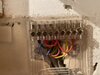
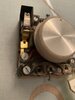
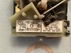
I’ve just moved house and found myself with a Ideal Mexico Super ideal C125 boiler, Horstmann 425 control and Sunvic thermostat. I’d like to replace the control for a hive but need some assistance with the wiring please.
I’ve attached a couple of pictures.
Thanks in advance!
David
 

Attachments

  • 4FB5C8C9-DE9E-47CA-AFAE-7FBC8C500722.jpeg
    4FB5C8C9-DE9E-47CA-AFAE-7FBC8C500722.jpeg
    344.4 KB · Views: 144
  • 09691E12-E7D8-44BB-9CD6-0FDD4EA5ACCF.jpeg
    09691E12-E7D8-44BB-9CD6-0FDD4EA5ACCF.jpeg
    230.4 KB · Views: 119
Sponsored Links
This has been asked before, you can find an example that should help you here.

There should be a diagram on your Sunvic thermostat somewhere; maybe the lid, that shows where the L, N and Switched L wires are terminated. The L and SL need to be bridged / connected and the N isolated safely.

EDIT
As you don't describe the type of plumbing the controls are connected to, I forgot to add: If you have a fully pumped system with motorised valves then the Hive is already set for that. Much less common now, but if you have an older system with just pumped central heating & natural (gravity) circulation of hot water, the Hive should be changed to gravity mode. The Hive instructions will tell you how to do this
 
Last edited:
  • Thanks
Reactions: CBW
Hi,

thanks for your reply. I did see that post but I wasn’t too sure what to do within my own thermostat. Linking out L and SL makes perfect sense.
Thanks again.

David
 
Ideally it's best done at the origin of the cable if you know where it is. Note where the individual wires are connected, disconnect the cable, then insert a link between the terminals where the L and SL to the thermostat have just been removed from.

The old thermostat and its cable can then be removed completely.
 
Sponsored Links
Hi looking into this further, there is only a live and neutral on the thermostat with a resistor.
 

Attachments

  • F68CA84B-C6BF-41A1-82B3-34142F60F0A4.jpeg
    F68CA84B-C6BF-41A1-82B3-34142F60F0A4.jpeg
    296.1 KB · Views: 67
As above you dont have a neutral , you have a live and a swtched live
 
As it is switching a load well under 13A it should have had a neutral connected to terminal 4 as shown in the diagram, so its working accuracy wouldn't have been very good. However as has been said, it's only the L and SL you are interested in. If there was a neutral wire it wouldn't be required anyway .....
the N isolated safely.
 

DIYnot Local

Staff member

If you need to find a tradesperson to get your job done, please try our local search below, or if you are doing it yourself you can find suppliers local to you.

Select the supplier or trade you require, enter your location to begin your search.


Are you a trade or supplier? You can create your listing free at DIYnot Local

 
Sponsored Links
Back
Top