Installing isolator/cut-out before CU

Joined
1 Sep 2008
Messages
1,066
Reaction score
35
Location
Bedfordshire
Country
United Kingdom
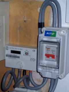
I'm having my meter changed next week, and I'm taking the opportunity to insert an isolator into the tails. I've checked with the REC and they won't install one (not even an option to pay them for one), but they are happy to wire the isolator back into the meter during the job.

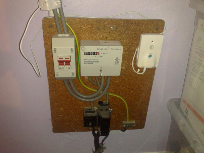
I've bought an MK 2-module enclosure and a 100A 2-pole switch, as well as several metres of 25mm tails. I'm scratching my head a bit on a couple of points...

1) Should the outer sheath of the tails be removed prior to the cable entry point, so that live and neutral can be identified by colour, without opening the enclosure? I've seen this on meters and was wondering if that's best practice or just a way to get fat cables through the holes!

2) The enclosure came with a couple of grommits that appear to be to meet an IP rating. Must these be used? My feeling is that they only appear suitable for a single round cable each, and there is only one hole at the top and one at the bottom. With two 25mm tails in each hole, there isn't really room to poke a screwdriver in there unless you're REALLY determined.
 
Sponsored Links
Don't worry about the grommets if you do not require the IP rating. I prefer to strip the cable within the enclosure and mark the tails with blue and brown tape. Otherwise the cable will not be double insulated to touch. Unstripped 25mm cables will go into a meter terminal hole if you cut it to the right length.

I would recommend you use a 4 module box with two blanks fitted. It will be much easier to terminate the tails. It can be done in a 2 module box, but won't be easy, unless you've done it before!

Also, bring all four cables out of the bottom of the box if you can. You can always cut your own holes.
 
Afaict it is technically a violation of BS7671 to have the inner insulation visible but some DNOs (who tend to work to thier own rules not BS7671) seem to insist on it for connection to meters etc.

I know and electrician who after getting messed arround about identification issues with tails too many times decided to order some with both layers of insulation the same color.

As for maintaining the IP rating how you acheive that is up to you. Putting a blank in the original central hole and drilling seperate holes that are a tight fit for each tail may be the easiest way.
 
Thanks guys.

I think I might need to buy a different enclosure! Any that you've tried that did the job well?

Problems with using this 2-module box are:

1) There's no way I can fit two tails through one of the original holes without severely chaffing the sheath (*snigger*)

2) To have all four cables coming out the bottom would require making one large hole for all four cables... Is this allowable?

3) To have all four cables coming out of the bottom would require putting a bend with a radius of about 1.5cm into one of the tails! What is the minimum bend radius for a 25mm tail?

Has anyone successfully used an MK 2-module box to install an isolator and 25mm tails? How is it done?! :eek:
 
Sponsored Links
the DNO mark theirs with coloured cable ties..
you can do the same, or with heat shrink..
 
This is mine. My DNO insisted on stripping back the insulation where it goes into the meter. I chose a Merlin Gerin switch, as it is rated a bit higher at 125A, a bit more robust.

The enclosure is WF's, chosen as it has a cover. This stops the switch being accidentally knocked: the MG DP isolators don't need a huge force to throw the switch.

The enc. is also really robust and does not flex, unlike cheaper offerings and has 4 sturdy screw fixings for the front cover.

To get the holes in the right places, I fitted the DP switch in the enclosure and measured where the tails would need to exit and enter in order to fit into the iso terminals without any bending, then drilled 4 holes just big enough for the tails to pass through. Those holes at the top I sealed up to make IP4X.


isolator.jpg
 
Suggest you don't mess around. Buy a Wylex REC2 isolator. You can get them from Neweys/CEF/etc.

Made for the job, nice and chunky and have mouldings to support the tails:

Nice one, thanks for that. I've got half a dozen CEF's round here so I'll drop in and pick one up.

Annoying thing is that the whole REC2 assembly is cheaper than the MK enclosure was on its own! What to do with a 2-module enclosure... :LOL:
 
On the isolator that British Gas (well, technically Siemens who they subcontract it to) installed for me, for the tails between meter and isolator they used double insulated ones that have both layers coloured. Even so, the guy still put coloured sticky labels round them that have L and N marked. He also put these on the (old 18mm) tails from the cutout where they went in to the meter.

For the tails I installed coming out of the isolator, I just applied a bit of tape to indicate L and N...
 
I was replacing the CU (yes I notified my LABC etc), so wanted to be able to put the new one in without having to break any of the DNO seals, or (shudder) work live...
 
Thanks to all for the advice! I obtained a REC2 from a local factors for £14, fitted it to the board and added the tails out of the bottom of the REC2. The meter fitter then wired it in when he came.

The end product.


The electrician who did the last rewire did a neat job of the tails (now pulled about a bit in the picture) so with the further-reduced space there isn't room for the sensor for the wireless power meter. That will change when I replace the CU later (yes, notified, Part P) and leave more room for the clamp.

So I now have a 100A MK isolator and 2-module enclosure for the spares box!

I can definitely recommend the REC2 - very easy to fit. Plus it identifies the conductors on the OUTSIDE of the box. Very useful.
 
On the service fuse at the bottom of the photo, what has happened to the lower part of the service fuse unit (i.e. the tapered bit that covers the incoming cable cores)? - it appears that the inner cores of the live service cable are exposed, where the outer covering has been trimmed back by the DNO - that part is normally enclosed by the taper lower section.
 
I cannot see any protective equipotential bonding on the Main earthing terminal. Does it terminate at the Consumer unit?
 
On the service fuse at the bottom of the photo, what has happened to the lower part of the service fuse unit (i.e. the tapered bit that covers the incoming cable cores)? - it appears that the inner cores of the live service cable are exposed, where the outer covering has been trimmed back by the DNO - that part is normally enclosed by the taper lower section.

These aren't always fitted. A lot of the cut-outs round here, especially from overhead cables don't have them.
 

DIYnot Local

Staff member

If you need to find a tradesperson to get your job done, please try our local search below, or if you are doing it yourself you can find suppliers local to you.

Select the supplier or trade you require, enter your location to begin your search.


Are you a trade or supplier? You can create your listing free at DIYnot Local

 
Sponsored Links
Back
Top