Lighting puzzle

Thanks guys.

Iggifer: I have a PIR sensor outside my garage door, two outside lights either side of the garage door and then three outside lights at the side of the house. When I moved in, (the now two switches) inside the garage were on a 2 gang switch and the left hand switch had a piece of electrical tape over it suggesting not switching it. The right hand gang switched the inside garage lights on and off.

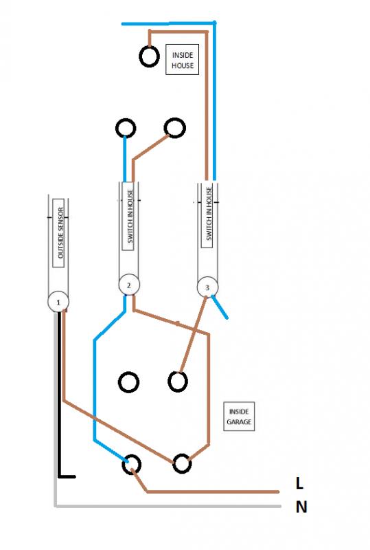
RF Lighting: The 2 gang inside the house I'm sure allowed me to override the outside lights but I never really got the hang of what they were doing. I'm made a sketch of the configuration if that helps:

24cffnm.jpg


EFLImpudence: The grey wire is going to the outside PIR sensor.

Thanks again for your help guys, really appreciate it.
 
Sponsored Links
Then I guess your neutral loop in the left hand switch is not being used as an N-Loop as otherwise operating the right hand switch inside would cause a dead short - and a bang.

Do you have a multimeter? I don't think there's a way to solve this without some testing.
 
Thanks iggifer. No I don't have a multimeter. Which one would you suggest I buy? I also fancy buying a fluke voltage and continuity tester - would this do the job or not?

Thanks again, really appreciate it.
 
A fluke will definitely do the trick. Got one in mind?

I am a big fan on the T5's, the T5-1000 is my day to day multimeter, but the T5-600 will be more than adequate for your needs

http://isswww.co.uk/fluke-t5600-electrical-tester

It's super simple, auto ranging (so you just choose Amps, Volts or Ohms)

If you're thinking a bit cheaper, the T110 will do everything you need, it just doesn't give you an actual read out

http://isswww.co.uk/fluke-t110
 
Sponsored Links
So in my situation a:
T5-600
T5-1000
T90
or
T110

Will all do the trick? It just depends how much I want to pay?

Is there any of the above that you would recommend for a "longer term investment"?

Thanks
 
They will all do what you need them to do - continuity and voltage readout

The only difference between the T5-1000 and T5-600 is that one is rated up to 600V and one is rated up to 1000V, care to guess which?

I'm sure the T5-600 will be more than enough for you.

The reason I prefer the T5 over the T90/110/120 etc is that the probes are not rigidly fixed to the body - snapped my T150 in a very short space of time.

The T5 also has an open jaw clamp meter - you'll probably never use it but it's there.

Overall, I'd recommend you go for the T5-600, others may have an opinion, but that's mine.

That being said, this is a steal. http://www.amazon.co.uk/Fluke-T5-10...e=UTF8&qid=1427748317&sr=8-1&keywords=t5-1000
 
That is a pretty good price. The case is a good investment - depending on where you're likely to keep the tester - mines in my toolbag so it keeps it protected and keeps the leads tidy.

If its going to be in a drawer, on a shelf in a shed/garage etc don't bother
 
Right... the fluke has arrived! T5-1000 Iggifer :)

To solve the original lighting puzzle, what would you suggest doing?

Thanks again for your help guys.
 
Using the new fluke I've added some more information to the diagram:

5dmfkn.jpg


33z7dox.jpg


Please can anyone help me solve what is happening now and work out what control I have over the lights? I'm guessing that the switches inside the house give manual control of the outside lights? Not sure why it's a two gang though? I'm also guessing that the grey core coming from the outside sensor shouldn't be connected to neutral?

Thanks for any help/advice you can give me here.
 
I think you will have to tell us what the Grey and Black are connected to at the sensor.

Can you do that without to much bother?
 
Here we go:

2zrl2qt.jpg


The twin and earth are supplying the two eternal lights above the garage door. This used to activate on the sensor correctly. The wiring in the sensor has definitely not been touch be the "electrician" by the way :D

Does that help?

p.s. more earth sleeving required I notice too!
 
I can't (be bothered to) figure out what has been done so:

Let's start again.
Firstly - do this and disconnect all the other wires and ensure they are terminated in separate connector blocks.


This will enable the outside lights to be controlled form both switches.
It can then be modified if you want to alter anything afterwards.
 
Thanks. Just tried that but it's not having the desired effect. It's switching the black core of the sensor live that's all. Although I'm not convinced that the outside lights that are run off the sensor are working so I best check those bulbs first hey!
 

DIYnot Local

Staff member

If you need to find a tradesperson to get your job done, please try our local search below, or if you are doing it yourself you can find suppliers local to you.

Select the supplier or trade you require, enter your location to begin your search.


Are you a trade or supplier? You can create your listing free at DIYnot Local

 
Sponsored Links
Back
Top