Method to locate a short in a cable run.

Joined
6 Aug 2011
Messages
3,191
Reaction score
192
Location
London
Country
United Kingdom
Following on from my previous thread, that has been zapped by Moderators, who only see me of using inappropriate language, I do not wind up people on here first, nor start offending anyone first, but if someone starts at me, and Moderators do nothing, I don't stand back and swallow insults. But I have learnt not to retaliate, but I will click on the post for moderators' attention. I will from now on use "report post" button.

Any ways, I found a novel way to figure out exact spot where a short circuit occurs in run of cable which may be buried under floor or under plaster.

1. First you measure the total run of the cable, one can guess how this cable must have run from a CU to its final termination point, measuring as accurately as possible, most cables runs would take a short logical and obvious paths. (Total cable length = TCL)

Once you have measured the length, irrelevant what units you use, metric or imperial
then get hold of a constant current power source, like 0 - 30V, 5amp current limited power supply. It must provide constant current.

2. Isolate cable at both CU and at the appliance end, unscrew wires from their terminations.
If the short is between say the live conductor to earth, then remove live conductor and its earth conductor which is likely where the short is between these two conductors.

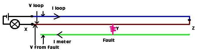
3. Attach power source to the Live and earth conductor at the CU end and accurately measure the voltage as 5 amps flow through this shorted pair (E & L)
note this voltage reading. (V1)

4. Now do the same at the appliance end, feed 5 amp constant current and measure the voltage and note this voltage (V2)

from this formula below you can now work out exactly how far the short circuit fault is from either end i.e. CU end to fault (V1) or Appliance end to short circuit (V2)

Formula: Total Length of cable (TLC) divide it by voltage V1+V2 and multiply by voltage V1 to get distance from CU to fault or multiply by V2 to get distance from appliance end,

I tried this on a 7 meter 0.75mm cable and had a deliberate short at 2 meters from one end, and the results were astonishingly accurate to within a few inches of the fault.

I am going to use my technique to find out where that short is on that shower cable and hopefully we won't have to dig out the entire floor or rip plaster off the wall unnecessarily.
 
Sponsored Links
There is a similar method that does not put current through the fault and hence is not affected by the resistance of the fault.


The current into the meter ( assuming high impedance digital meter ) is very small and the voltage drop along the earth due to the meter current can be ignored.

The current I loop only has to be constant while the two voltages V loop and V from fault are measured so a battery and lamp are adequate as a source.

If V fault = 1/2 V loop the fault is at the far end
If V fault = 0 v then the fault is at the near end.
The distance to fault is determined by

d = Length ( V fault / ( 0.5 * V loop )

If the fault is a Live to Neutral then use the Live and Earth as the loop an the Neutral as the sense wire to the meter. The difference is impedance of the Live and Earth wires means the voltage at the far end is not V loop / 2 and has to be calculated from the CSA of the Live and Earth conductors
 
Last edited:
Nice one Bernard. In your set up you do not require a high amount of constant current source, and of course the fault resistance can play significant role in not achieving accurate prediction of the site of the fault, especially if it starts changing as the heavy current passes through it. However I am going to try and see how it goes at this place where the shower circuit has a fault between Live and Earth which reads 1.2K , my power source is limited to 35v maximum at 5.5Amps, so I am not sure if I will get any luck with my set up, though in theory and in a dead short circuit scenario it would work pretty good.

I deliberately introduced cable length error, so instead of being say 8 meters, I used 7 meters, the prediction still covers the fault area but widens it by 600mm, still better than guessing wild.

If my set up does not work (due to high resistance of the fault and low MM test voltages) I may give your set a go, first I must study and absorb how your set up works, I had a quick look and a little confused when you said you also need to work CSA of the cable. (Is this because earth cable is smaller in CSA than normal power conducting conductors?)

(A simple Resistance measurement of the cable is not sufficient to provide accurate results as resistance measurements use very low current, and measurements are not displayed accurate to 3 decimal places, hence the use of high current to measure small voltage drops to 3 decimal places on a DVM)
 
Any ways, I found a novel way to figure out exact spot where a short circuit occurs in run of cable which may be buried under floor or under plaster.
I wouldn't say it's 'novel'. Measuring resistance from both ends is a standard (and obvious) method, and that's essentially what you are doing - you are proposing an improvised method which allows you to effectively measure small resistances fairly accurately. If you had a precise milliohm meter, you could do it with that.

Unless you actually measure the current accurately, and then adjust your calculations accordingly if it differs for your two measurements, your method obviously relies on the power source limiting current to a very consistent figure - which, in my experience, is not necessarily the case with 'standard' current-limited power supplies.

Kind Regards, John
 
Sponsored Links
John, thanks for your comments, milliohmmeter are not what everyday Electricians posess, it is a lab gear, whilst it can't be difficult to get hold of bench power supply readily for about £30 to £90.
Most Digital Multimeters have the lowest Resistance range of 200 Ohms, that means they cannot measure resistances as low as 0.001ohms , so in order to measure resistances as low as this one needs mighty current source and again how many amps it will depend on the cable CSA, the bigger the cable the higher the current with a short span, but long cables would naturally posess higher overall resistance so a lower current can be used. ( of course many of you may say that heavy current can actually fuse the fault area, still the test current is many times lower than the actual fault current that tripped the MCB.)

It is a novel method , novel in a sense it is very simple and readily doable, you don't need highly specialised instruments) as we were discussing last time, hardly anyone proposed how to trace a location of a S/C fault, Did anyone else apart from Bernard here suggested how I could have traced this S/C fault with any method other than what we had discussed like I suggested using a more sophisticated method of using high frequency (Kilo hertz) signal down a shorted loop and tracing its energy using a resonant circuit tuned to that frequency. I suppose some things would be outside the scope of average electricians as this branches more into electronics.

This method would of course work where a nail has gone through a cable shorting its inner earth conductor to one of its other power conductors, it may not provide accurate reading if the fault developed where one of the conductor was in contact with an external earthing body, because external bodies cannot be consistent like the inner earth wire.
 
Last edited:
You do seem to be being very cantankerous in these threads.

You only posted a 2.56am today.

If you want to do Electrical work then you need the correct tools.
You have said you have some unusual equipment but baulk at getting what you actually need.
 
I've been watching this thread as it started off looking interesting, but its gone down the tube comme d'habitude. :rolleyes:
So I'm out bye..........
 
John, thanks for your comments, milliohmmeter are not what everyday Electricians posess, it is a lab gear
Sort-of true, which is why I said that what you were doing was simulating an item of test gear which you don't possess. I say 'sort-of', because the MFTs routinely used by electricians (not 'lab gear') usually have a resistance-measuring resolution of 10mΩ (0.01Ω) or lower, and that's probably adequate to get a reasonably good estimate of the location of a fault in a reasonable length of a modest size (say up to 2.5mm²) cable.
... whilst it can't be difficult to get hold of bench power supply readily for about £30 to £90.
Indeed, but, as I wrote/implied, the current limiting in a bench power supply costing £30-£90 is there primarily as a protective measure, with no guarantee that (in the face of a very low resistance load) it will limit the current to a consistent figure - for 'precision current limiting' you would again need 'lab gear'.

Kind Regards, John
 
I've been watching this thread as it started off looking interesting ....
Is not getting a measure of resistance (one way or another) between conductors at both ends of the cable what you would do in order to get an estimate of the location of a short within it? I suppose I must be wrong, but I had assumed that's what any electrician would do, at least in the first instance.

However, Bernard's method (which he has described before) is probably preferable, since it does not rely on having access to a power supply with precision current limiting.

Kind Regards, John
 
This method would of course work where a nail has gone through a cable shorting its inner earth conductor to one of its other power conductors, it may not provide accurate reading if the fault developed where one of the conductor was in contact with an external earthing body, because external bodies cannot be consistent like the inner earth wire.

It is possible to use the ground as the meter lead ( from meter to fault location ) if the current through the meter is extremely low and the power supply for the test current is fully floating with no leakage ( or capacitance ) to Ground. A battery and resistor ( or lamp ) being ideal.

Using Wheatstone bridge techniques instead of a volt meter can give very accurate results when tere is no option other than using the Ground as the "meter" lead.
 
Yes John, there are draw backs in every thing, most things won't provide consistent readings, not even my blood sugar testing machine, if you try taking a second sample seconds away, in fact by using the same blood, it will give you a different reading, not even close to 0.1 (tenth accuracy) so the same blood sample could indicate 5.7mmol, another sample taken immediately from the same pack of tester strips can show a reading of 6.4mmol. Same goes for everything. This includes gas analysers, many times my car fails on its emissions at first attempt, and the MOT tester runs a second attempt and it passes, seems like the whole universe is inconsistent.

Bernards method also has a draw back, as the bulb draws current, the battery looses charge, its terminal potential starts coming down, so by the time you hook the other end of the cable to the tester, the voltage may have gone down by about 100mV to give inconsistent readings. All methods have draw backs, in theory my set up was accurate to 2 inches, despite I measured the length of the cable accurate to 1 inch. but if a cable is buried in plaster or underfloor, you have no chance of getting it close to 1" difference to its actual length. So yes, it is not a pin point system, but say within a meter, and when you know where you should be looking, you will usually find obvious signs of things which may have caused the cable to be ruptured etc. in that vacinity.
 
Bernards method also has a draw back, as the bulb draws current, the battery looses charge, its terminal potential starts coming down, so by the time you hook the other end of the cable to the tester,
With the battery disconnected you go to the far end and connect Live and Earth together.
Then at the battery end you connect the current to the loop and measure the two voltages within a couple of seconds of each other.
 
Yes John, there are draw backs in every thing, most things won't provide consistent readings ....
Of course. there is always measurement error and variability. However, measuring equipment, such as your blood glucose machine, a multimeter or whatever, is at least designed to be reasonably accurate and consistent. In contrast, a cheap current-limited PSU is probably not - it merely seeks to limit the current to some approximate level adequate to protect itself and/or the load from excessive current. Think of the protective devices we use in electrical installations (MCBs, RCDs, RCBOs etc.) - the range of acceptable 'trip thresholds' is pretty wide, the important things being the 'ceilings', above which the threshold is not allowed to go. An RCD with an IΔn of 30mA is certainly not guaranteed to only operate if the residual current actually reaches 30mA - it would commonly operate at 20 or 25mA. Similarly, I would not be surprised, and would not 'complain', if a cheap "5A current-limited PSU" sometimes limited the current to 4.8A or 4.5A.
Bernards method also has a draw back, as the bulb draws current, the battery looses charge, its terminal potential starts coming down, so by the time you hook the other end of the cable to the tester, the voltage may have gone down by about 100mV to give inconsistent readings.
Only a relatively small current is required. If the voltage fell by 100mV in the time it took you to hook the other end of the cable to the tester, I think you should probably be looking for a better and/or bigger battery!

Kind Regards, John
 
Yes John, I can tell you the bench power supply I have has a variable current setting to it, so it has a feedback loop that maintains the set current to a very precise accurate level, and it is fan cooled so that abnormal temperature rise does not effect its performance and chosen settings, if you want to argue about my ability, and everything else then carry on. You are welcome to criticise me, but I can assure you I wasn't born yesterday, I do have oceans of experience in many fields.

However, I am also honest, I admitted where I was wrong when I had discovered my mistake, it was my oversight on that RCB issue, I admitted my error and apologised to those and you who said otherwise that what i said can't be right. I also did have my doubts, but i overruled my doubt by getting mixed up with the fact that I assumed one can protect live only if required without protecting Neutral, using an electronic sensing relay type breaker. Where small leakage current to earth could trip the relay off, slightly different in principle to RCD operation.

And now the bad news, my set up did not work, and it does not mean I cannot deploy my theory in future on other installations to locate earth faults on buried cables where the short is in order of a literally zero ohms, or under 1 ohm. I did doubt if it would work here due to 1.5K ohm impedance, it did not even draw any registerable current on my bench power LCD display, it remained at 0.00, frequently seen to jump between 0.01 and 0.00, this is just a basic LCD module used on it, not a high accuracy device, and the influence of other mains cables possibly running next to it.

what I applied was maximum 32V. I left it connected for almost 2 hours, and still it did not register any current, though in reality it must be drawing 32/1500 > 20mA, I left it on, and came back home to have some tea break, went back half hour later, I removed the power from the leads, and checked fault impedance if it had changed, it went right up to 10K ohms.

So we will never be able to pin point its location using any methods, I tried another method and it also failed to detect due to high impedance nature of the fault.
But we sure know that when connected to mains voltage all hell breaks lose, and it trips 40A MCB as well as the unrelated RCB.

Back to drawing board, and the only method now is to get on with the job, rip off all tiles and plaster and dig it out. we wanted to avoid this.

Let you know when we get to the bottom of this what was the cause or nature of this fault, my money is on his recent burst pipe leaking water in his concrete floor laden with water and CH pipes running all over, including to bathroom which lead water to this buried cable, and who knows there may be a JB, concreted over through which water is making a contact between L & E and not between N & E.

So let us not get into that rut again, you knocking my abilities, I do not knock other people's abilities on here when I know they are often wrong. I used to carry out electrical work over 30 years ago, now things are different, so many things I don't know and I don't claim to know everything, hence why I come here, and I get very hostile reception. If you simply don't want me to be here, thats fine, I won't mis much, I will get my account deleted.
 
Last edited:
Also my thanks to Bernard, I would like to try his idea but i doubt it would work due to high impedance fault. He is someone on here I highly respect, because it takes one to know the other.
 

DIYnot Local

Staff member

If you need to find a tradesperson to get your job done, please try our local search below, or if you are doing it yourself you can find suppliers local to you.

Select the supplier or trade you require, enter your location to begin your search.


Are you a trade or supplier? You can create your listing free at DIYnot Local

 
Sponsored Links
Back
Top