Morning
We've finally plumped for a nest persuaded by the slight Black Friday reduction.
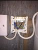
I'd read a few reviews beforehand and most advised they were easy enough to install (I suppose that is dependant on the installer!), I've had a quick look at the current set up, which has the mains switch in to the control unit. Please see picture.
I thought it could be as easy as replicating the current set up using the 230v diagram, but thought I'd check first and have worried myself that a wrong wire somewhere would blow the PCB, so just to check, any advice on what goes where in the heat link would be appreciated, failing that my father in law is an ex gas engineer and could do it for me on his next visit, but my impatience strikes again.
Thanks for any help.
We've finally plumped for a nest persuaded by the slight Black Friday reduction.
I'd read a few reviews beforehand and most advised they were easy enough to install (I suppose that is dependant on the installer!), I've had a quick look at the current set up, which has the mains switch in to the control unit. Please see picture.
I thought it could be as easy as replicating the current set up using the 230v diagram, but thought I'd check first and have worried myself that a wrong wire somewhere would blow the PCB, so just to check, any advice on what goes where in the heat link would be appreciated, failing that my father in law is an ex gas engineer and could do it for me on his next visit, but my impatience strikes again.
Thanks for any help.