NEST Installation

Joined
3 Dec 2019
Messages
36
Reaction score
2
Country
United Kingdom
Hi all, first post here! Please move if it's in the wrong section.

I'm quite into my DIY and have been upgrading parts of the house, I bought a Nest thermostat last week and just wanted to check everything checks out, if anyone could give any advice on the below it would be greatly appreciated!!

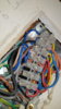
I removed my old programmer in the Kitchen, I plan to place the nest 'Heat Link' here in it's place. There are a couple of things I wanted to check first.

Wiring diagram I figured below:
H21XL ----> NEST Heat Link
N --> N
L --> L
1(HW ON) --> 6 (Call for Heat HW)
4 (CH ON) --> 3 (Call for Heat CH)

L-2-5 linked Common.

There are currently no T1 or T2 wires behind the programmer, I am guessing these are located upstairs in the tank cupboard but I cannot see where. Meaning I will be just using USB mains power for the actual Nest stat to avoid chasing new wires around. What's the best way to locate and disconnect the old thermostat wires so they don't sit live in the walls?

I gather I have an S plan system as there are 2 valves upstairs in the tank cupboard and there are no HW off or CH off wires to the programmer. There is a thermostat on the tank upstairs also, leading me to believe the HW is just stat satisfied? Only problem with this is I read online the Nest may require an extra wire from this stat into the HW off slot so the CH isn't turned off once the tank is at temperature, is this true or can the system run separate as it is now with just the 4 wires connected? (Along with the L-2-5 too)

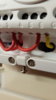
In the tank cupboard upstairs there is a blanking plate with 6, 5, 2 and 1 above it colour coded, my interpretation would be:
6 - CH off
5 - Common
2 - Common
1 - HW on

Are these relevant for this installation or can I leave these as is?

I can provide more info or pictures if needed, I have an ideal vogue s26 boiler.

Thanks to anyone who can help!
 
Sponsored Links
20191203_091937.jpg
20191203_102615.jpg
20191203_102036.jpg
20191203_115653.jpg
 
Wiring diagram I figured below:
H21XL ----> NEST Heat Link
N --> N
L --> L
1(HW ON) --> 6 (Call for Heat HW)
4 (CH ON) --> 3 (Call for Heat CH)

L-2-5 linked Common.

That looks good to me. (y)

There are currently no T1 or T2 wires behind the programmer, I am guessing these are located upstairs in the tank cupboard
No, they won't be there T1 & T2 are a unique Nest requirement, they provide the 12v supply for the Nest thermostat from a power supply built in to the Heat link. If you don't want to install them a separate plug in power supply is the way to go

I gather I have an S plan system as there are 2 valves upstairs in the tank cupboard and there are no HW off or CH off wires to the programmer...... I read online the Nest may require an extra wire from this stat into the HW off slot
It's not the Nest that needs the HW off. Nest provides it for heating systems that have a 3-Port valve (Y-Plan) that need a 'HW off' signal to work. As you have 2-Port valves (S-Plan) it's not required.

To remove the old room thermostat, trace the cable from the thermostat back to its origin. Note where the wires are connected and remove them. Then insert a link to join together the two terminals where you have just removed the wires that went to the thermostat terminals (1) and (3) so that they are joined together. The old room stat and its cable can then be removed.

Alternatively, if you are happy to leave the old room thermostat in place, take the wires out of 1 and 3 and join them together with a new connector.
 
Last edited:
Thanks for your reply, it's good to know I'm almost there with it! What is the best way to trace the cables? Will they be connected directly to the boiler connectors?

Thanks again!
 
Sponsored Links
Unfortunately, the room stat cable could terminate in several places based on how the original installer decided how to wire the system up. The most common place is usually at the wiring centre (behind the blanking plate in your airing cupboard) in which case, the wire from thermostat terminal (3) should be connected to the brown (Live) wire of the central heating motorised valve. The second, but less common place is behind the programmer. When I think I've found it, I always check with a multimeter to make sure.

The one place it won't be connected though is the boiler. With S-Plan, the room and hot water cylinder thermostats control the motorised valves and so are wired to them. It's the motorised valves that then control the boiler.
 
Thanks again, I'll take a look on Thursday to see if I can get this done :D
 
Ok, so I took the plate off today and trying to figure out which wire(s) lead to the old thermostat and being honest, this wiring it probably a little out of my depth to figure out without a wiring diagram.. I have posted up some pictures of the wiring.

Which wires are most likely to be connected to the thermostat and using my multimeter, what is the best way to test this?

Thanks again for your help and advice.
 

Attachments

  • 20191205_100304.jpg
    20191205_100304.jpg
    304.7 KB · Views: 272
  • 20191205_094551.jpg
    20191205_094551.jpg
    248.6 KB · Views: 295
Difficult to see, there's not much room in there is there?

Normally the switched live wire from the room thermostat terminal (1) will be connected to the brown wire of the central heating motorised valve. Once you have a 'suspect cable' and noted where the wires go they should be disconnected and then with a multimeter set to measure 'Ohms' (resistance) and connected as below, get an assistant to turn the thermostat up and down. When it's on 'max' there should be a low resistance, and when it's on 'min' a high resistance.

photo.JPG


1.jpg


The wire colours above show one convention, but yours may be different, it's where they are connected that matters.

Yours though is a difficult installation to work on, and there is a danger that you may disturb other wires whilst making the tests. It might be easier to disconnect the cable and the wires at the thermostat end and put them in a junction box that can be relocated out of the way. The live wires that were in (1) and (3) would be connected together, and the neutral (if present) isolated. Electrically it achieves exactly the same thing. Except you wouldn't be able to use the cable for connecting to T1 & T2, but if you're planning on using a separate plug in power supply for the Nest Thermostat anyway, it doesn't matter.

2.jpg
 
I took your advice and connected the old thermostat lives wires via junction box and isolated the neutral. Fitted a blanking plate to ensure I know there are live wires and keeping the option for a future thermostat there. All fitted now, whipped out to buy the nest stand and fitted it in the living room.
20191205_123054.jpg
20191205_133435.jpg


Edit*

The nest has power and the heat link, but it is not calling for heat from the boiler currently even when it should be.. Any ideas for this?
 
Last edited:
This is what the boiler currently says:
 

Attachments

  • 20191205_135059.jpg
    20191205_135059.jpg
    87.6 KB · Views: 246
  • 20191205_135051.jpg
    20191205_135051.jpg
    96.8 KB · Views: 275
Sorry it's a bad angle, L-2-5 are linked.. 3 has the old CH on wire, 6 has the old HW on wire
 

Attachments

  • 20191205_141620.jpg
    20191205_141620.jpg
    101.4 KB · Views: 265
OK, that's fine then.

The Heat link should be showing 3 green lights when everything is switched on. Is it?

lights.JPG


Is the hot water working OK?

What happens when you press the centre button on the Heat link? It should manually switch the heating on & off.

Check the terminals are tight in L, 2 and 3. Heat links can be fiddly even when you are used to them. Check the original thermostat wires from 1 and 3 are securely connected together too.
 

DIYnot Local

Staff member

If you need to find a tradesperson to get your job done, please try our local search below, or if you are doing it yourself you can find suppliers local to you.

Select the supplier or trade you require, enter your location to begin your search.


Are you a trade or supplier? You can create your listing free at DIYnot Local

 
Sponsored Links
Back
Top