New Ceiling Fixture fitted, lights stay on, switch is off!?!

Update: I've bought one of those capacitor things and have tried wiring them into the light fitting and the dimmer switch - both ways still cause it the lamps to be dimmed when switched off.

This is really frustrating me, does anyone have any further suggestions or ideas?

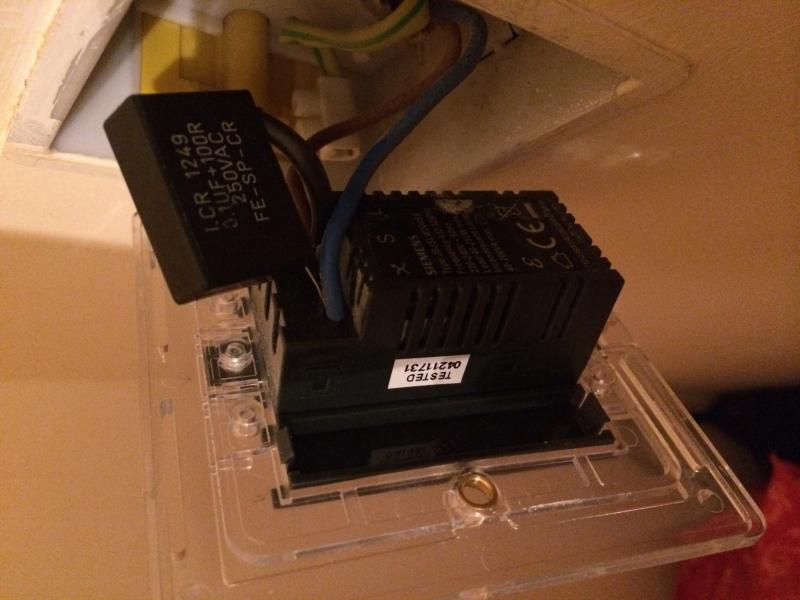
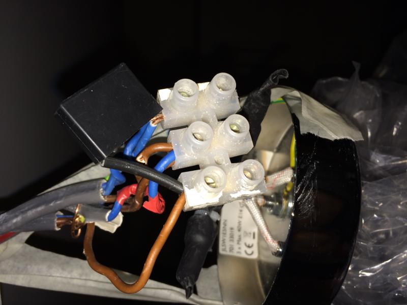
Pics posted below to show you guys incase I'm doing something wrong


Sponsored Links
You need a different light or a different dimmer. The two are totally incompatible. There is no other way to resolve this issue.

Sorry you were given duff advice about buying a suppressor. They are used for curing a completely different 'fault' to the one you have.
 
Sorry you were given duff advice about buying a suppressor. They are used for curing a completely different 'fault' to the one you have.
The "fault" is the same. A small amount of energy getting to the lamp when the switch is OFF.

Most common is the very low current through the stray capacity between the Live and Switched Live in the cable to the switch. 0.1μF + 100 Ω invariable absorbs that leakage current.

Almost all dimmers "leak" some current through their "switch" when they are OFF, this is what powers the electronics in the dimmer. Remote controlled dimmers have to "leak" enough to power their wireless receiver which has to be active all the time.

Putting a suppressor across the dimmer will increase the leakage current to the lamp.

I am surprised that the 1μF + 100 Ω did not absorb the leakage from the dimmer.
 
Sponsored Links
I too am surprised that this did not solve the problem, on every other post I've looked up I can see that the capacitor has solved everyone's problems - except mine - just my luck

From the images I've posted can anyone confirm if I've wired it in correctly or not - for the light fitting, the image shows it being wired into Live but I did also try wiring it into switched live before - i just didn't take a picture of this

Taylor - the second picture is of the light fitting, it's just not clear

is there anyway to test the Capacitor to check if it works - I was a bit skeptical when the guy in Maplin just handed it to me loose, although I can understand why
 
for the light fitting, the image shows it being wired into Live
No - it shows it connected to the switched live.

From top to bottom:

N loop in and out.

L loop in and out and the blue conductor of the switch cable. (Which should be marked with brown tape, not red, BTW.)

SL brown conductor of the switch cable.


And talking of what the picture shows...

screenshot_320.jpg


GREEN CIRCLE = oo-err, not good, should be cut back and reterminated. The N connections should also be re-done so that there's no copper showing.

RED SQUARE = Question - do all those earths end up connected together at the light fitting earth terminal?
 
It should be fitted between Neutral and Switched Live.

It looks correctly fitted in the picture.

The two wires from the lamp are the key to which terminals to use for the suppressor.

Without a multi-meter it is difficult to safely test the suppressor but the chance of it being faulty are virtually zero.

You can try turning the power off and then disconnect the dimmer and put the ends of the cable in two terminal blocks. Then put the power back on and see if the lamp still glows. If it does then there is another problem. Low insulation resistance between Live and Switched Live will give this dim glow effect.
 
Almost all dimmers "leak" some current through their "switch" when they are OFF, this is what powers the electronics in the dimmer. Remote controlled dimmers have to "leak" enough to power their wireless receiver which has to be active all the time.
Indeed - unless (rarely) they have a neutral connection.
Putting a suppressor across the dimmer will increase the leakage current to the lamp.
True, but that's obviously the last thing one would want to do - it would exacerbate the problem and could well stop the dimmer working (at all or properly), by undermining the powering of its electronics and/or wireless receiver. To address the problem (if it is due to the mechanism you describe), one would obviously connect the suppressor across the lamp.
I am surprised that the 1μF + 100 Ω did not absorb the leakage from the dimmer.
Me too - provided that the suppressor is across the lamp and IF the problem were due to the mechanism you have mentioned. This might cast doubt on whether such is the mechanism in action.

Kind Regards, John
 
L loop in and out and the blue conductor of the switch cable. (Which should be marked with brown tape, not blue, BTW.)
Just for the record, I presume that should read "red", not "blue". I think one thing which may have confused some people is:
I have traced the switch wire now - am going to put a bit of red tape over it.
... which I suspect some people will have interpreted as meaning that the red tape has been put on the S/L, rather than (as appears to be the case) the permanent L feed to the switch.

Kind Regards, John
 
We are not dealing with inductive leakage here, which is why the suppressor will not work.

What the op has is two loads in series. The dimmer has indicators on it which are connected in series with the lamps to derive a neutral at the switch.

This is where internet theory falls down and experience of actual contracting comes into play.

You can post about your surprise as many times as you like but it ain't going to cure the problem.
 
Just for the record, I presume that should read "red", not "blue".
It should indeed.

Because Umy has not been back yet (well - no evidence of that), I've changed it, to avoid confusion.


which I suspect some people will have interpreted as meaning that the red tape has been put on the S/L, rather than (as appears to be the case) the permanent L feed to the switch.
The purpose of the tape is to mark the blue conductor as a line, not neutral. It's not to mark the function of switched line. Most people would, I think, use brown as the permanent line to the switch, so marking the (blue) switched line would coincidentally identify the function, but that's not why it's taped or oversleeved brown.
 
We are not dealing with inductive leakage here, which is why the suppressor will not work. ... What the op has is two loads in series. The dimmer has indicators on it which are connected in series with the lamps to derive a neutral at the switch.
That's all true, other than that I think the 'suppressor' still ought to 'work', at least to some extent, particularly if the load (LED wattage) is low (it has worked for me). The impedance of a 1μF+100Ω suppressor is around 3.2kΩ at 50Hz. Viewed simplistically, the 'effective impedance' of, say, a ('100% efficient') 5W LED lamp is around 10.5kΩ. If one puts the suppressor across the lamp, then maybe three-quarters of the 'standby current' of the dimmer would go through the suppressor, and only one quarter through the lamp. If that isn't enough reduction in current (through the lamp) to cure the problem completely (or if the LED load were greater) increasing the value of the capacitor (putting 'suppressors' in parallel would be one way) should improve things further.
This is where internet theory falls down and experience of actual contracting comes into play.
Physics is the same whether contracting or 'DIYing'. Whilst I obviously don't do any 'actual contracting', I've certainly successfully addressed the issue we're talking about in the manner being discussed.
You can post about your surprise as many times as you like but it ain't going to cure the problem.
See above - it has worked for me in the past.

Kind Regards, John
 
which I suspect some people will have interpreted as meaning that the red tape has been put on the S/L, rather than (as appears to be the case) the permanent L feed to the switch.
The purpose of the tape is to mark the blue conductor as a line, not neutral. It's not to mark the function of switched line. Most people would, I think, use brown as the permanent line to the switch, so marking the (blue) switched line would coincidentally identify the function, but that's not why it's taped or oversleeved brown.
All agreed, but that was not my point. My point was that the OP told us he was going to put red tape on the "switch wire", and I think some may possibly have incorrectly read/interpreted that to mean "switched live".

Kind Regards, John
 
What is the actual standby current of the dimmer?
Numerically, you mean? I haven't much of a clue (and they probably vary appreciably), but I would guess that it probably isn't much more than a moderate handful of mA, at most. Whatever it's magnitude, it's path will obviously be shared between the lamp itself and anything [like 'suppressor(s)] in parallel with it, in inverse proportion to the respective impedances of those two parallel paths..

Kind Regards, John
 

DIYnot Local

Staff member

If you need to find a tradesperson to get your job done, please try our local search below, or if you are doing it yourself you can find suppliers local to you.

Select the supplier or trade you require, enter your location to begin your search.


Are you a trade or supplier? You can create your listing free at DIYnot Local

 
Sponsored Links
Back
Top