Newby Busy Breaking Electrics...

Joined
2 May 2011
Messages
5
Reaction score
0
Location
Avon
Country
United Kingdom
Hi all,

I've got a slight situation here.

A loop lighting system - going to the upstairs light circuit, has the ground floor hall lights on it.

The first light only has 1 core (r,b & e) - the second one has 4. I am assuming that the first light takes a feed directly from the second (it also shares the same switch).

In re-wiring in a new pendant for each of them - I have now caused a number of knock on faults.. Yeay!

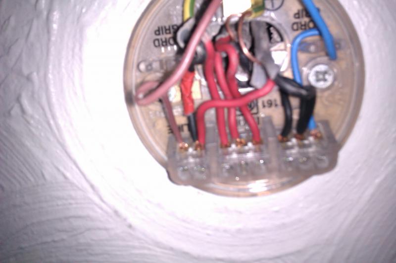
I identified the switched live, another set of cables set off the conntectivity tester (and don't switch with the switch). At the moment I have set it up with the

Switched live + other red cable from the "always on" into the first two boxes, then the three red loops followed by the rest of the neutrals into the last connectors.

This now means lights further on in the circuit require the 4 core light to be onto turn on themselves... Do I leave the always on red cable with it's mates in the loop connectors and just have the neutral in with the pendant neutral?

Cheers
 
Sponsored Links
Can you tell us whether the downstair hall and upstair landing lights are two way. Normally the downstair light switch will operate the upstair landing light which can also be operated by the upstair light switch?

If this is the case then the normal route is to wire this connection through the switches.

Which is the first light and which is the second light?

I also take it you mean 4 cables rather than a 4 core cable.
 
Hi,

Yes I meant seperate 4 cables, not cores.

The switch panel at the bottom of the stairs has two switches - one for the two downstairs lights, and one with a linked switch at the top of the stairs that controls the upstairs landing light.

From my point of view the first light is the one right by the front door, the second one is next to the bottom of the staircase. However as I mentioned above - it seems that this has been extended from the "second" pendant as it isn't linked to any of the rest of the loop's electrics.
 
If I am reading this right, one of the downstair switches controls two hall lights. I will assume that this one switch activates both lights at the same time.

If that is the case the one with the four cables will have.
Two cables for the live/neutral/earth loop. One cable that goes to the switch and returns as the switch live and the final cable will go from the first light to the second.

Ceiling rose with four cables..
Loop cables go to the Live, Neutral and earth at the ceiling rose.
Switch cable to switch (red/brown) goes in the ceiling rose live and the returning (black/blue - with red/brown sleeving) goes to the pendants live.
The fourth cable connecting the second light.....red/brown to the pendant live - the black/blue to the pendant neutral.
At the second ceiling rose. The red/brown goes to the pendant live and the black/blue goes to the pendant neutral.
Earth are also connected as per norm.

Check out wiki lighting.
 
Sponsored Links
Thanks,

I did have a quick look before posting and couldn't see the same issue being replicated there...

Have quickly checked it out - it seems to be set up as you outline, however now the upstairs lighting works (inpedendantly switched from their switchs) as long as the downstairs gf light switch is on & the front gf light is constantly on!

So obviously I am going wrong somewhere :(
 
Okay lets just check what you have done.

Have you altered anything in the light switches?

If not check how the light switches are wired. Are there any terminal strips in the backbox?

For a single switch operating the downstairs (two) lights you would expect a live(red) in Common and a switched live (black with red sleeving on) to be in L1.
For a two way (link to upstairs) there should be a three core cable connected to Common L1 and L2 - or - a two core cable and three core cable connected as per wiki. There are other ways to wire it but this is what I hope you would see.
 
Haven't touched the switchs, apart from to ease away from wall for lining paper behind, and to take the pic attached.


The rose is wired as follows:

Apologies for the pics but the daylight is gone + I'm not going to play with live electrics...
 
Apart from the amount of copper on display everything looks right at the ceiling rose. I will assume that you took note of how the old ceiling rose was wired and wired the new one the same.

The picture of the switch is a little unclear.
Looking at the picture I take it the rear of the first switch operates the upstairs light and the furtherest switch operates the downstairs light.

I would normally expect to see three core wire here - but it possible that the switches have been wired using the conduit method. Are these single cables or is just the angle of the photograph?

//www.diynot.com/wiki/electrics:lighting:two_way_lighting - scroll down for conduit method.
 
If only I had... After getting hands on a multimeter I thought I could crack it, but obviously its not that simple.

Its seperate cabling between the terminals - just the angle makes it look like one wire. Lefthandside of the pic is the downstairs, rght up.
 
Thanks,

I did have a quick look before posting and couldn't see the same issue being replicated there...

Have quickly checked it out - it seems to be set up as you outline, however now the upstairs lighting works (inpedendantly switched from their switchs) as long as the downstairs gf light switch is on & the front gf light is constantly on!

So obviously I am going wrong somewhere :(

Assuming the switches worked before lets leave them alone and concentrate on the ceiling rose.

Are you sure that you have correctly identified the Twin & Earth containing the switch live and the Twin and Earth that links to the second light.
The reason I say this is the fact that the front ground floor light is constantly on despite what the switch is doing tells me that it is connected to the live loop.
I feel you may need to clarify this with the multimeter - doing continuity tests while the circuit is dead - but better wait until the morning.

To do a continuity test - make sure the circuit is dead - then connect in a terminal block what you think is the live and neutral of the cable link to the second light. Set the multimeter to low ohms and test between the live and neutral at the second light. A low ohm reading will indicate continuity and you have identified the cable.
Then do the same for the switch wire at the ceiling rose and the switch itself until you establish which is the switch wire.
Then wire as outlined above.
 

DIYnot Local

Staff member

If you need to find a tradesperson to get your job done, please try our local search below, or if you are doing it yourself you can find suppliers local to you.

Select the supplier or trade you require, enter your location to begin your search.


Are you a trade or supplier? You can create your listing free at DIYnot Local

 
Sponsored Links
Back
Top